Information injection-pump assembly
BOSCH
F 019 Z20 171
f019z20171
ZEXEL
106681-4460
1066814460
NIIGATA-TEKKOU
75L47530A
75l47530a
Rating:
Service parts 106681-4460 INJECTION-PUMP ASSEMBLY:
1.
_
7.
COUPLING PLATE
8.
_
9.
_
11.
Nozzle and Holder
12.
Open Pre:MPa(Kqf/cm2)
25.5{260}
15.
NOZZLE SET
Include in #1:
106681-4460
as INJECTION-PUMP ASSEMBLY
Cross reference number
BOSCH
F 019 Z20 171
f019z20171
ZEXEL
106681-4460
1066814460
NIIGATA-TEKKOU
75L47530A
75l47530a
Zexel num
Bosch num
Firm num
Name
F 019 Z20 171
75L47530A NIIGATA-TEKKOU
INJECTION-PUMP ASSEMBLY
DMF13HZA * K 14CA INJECTION PUMP ASSY PE6P,6PD PE
DMF13HZA * K 14CA INJECTION PUMP ASSY PE6P,6PD PE
Calibration Data:
Adjustment conditions
Test oil
1404 Test oil ISO4113 or {SAEJ967d}
1404 Test oil ISO4113 or {SAEJ967d}
Test oil temperature
degC
40
40
45
Nozzle and nozzle holder
105780-8250
Bosch type code
1 688 901 101
Nozzle
105780-0120
Bosch type code
1 688 901 990
Nozzle holder
105780-2190
Opening pressure
MPa
20.7
Opening pressure
kgf/cm2
211
Injection pipe
Outer diameter - inner diameter - length (mm) mm 8-3-600
Outer diameter - inner diameter - length (mm) mm 8-3-600
Overflow valve
134424-4120
Overflow valve opening pressure
kPa
255
221
289
Overflow valve opening pressure
kgf/cm2
2.6
2.25
2.95
Tester oil delivery pressure
kPa
255
255
255
Tester oil delivery pressure
kgf/cm2
2.6
2.6
2.6
RED3 control unit part number
407910-3
960
RED3 rack sensor specifications
mm
19
Direction of rotation (viewed from drive side)
Left L
Left L
Injection timing adjustment
Direction of rotation (viewed from drive side)
Left L
Left L
Injection order
1-4-2-6-
3-5
Pre-stroke
mm
3.2
3.15
3.25
Beginning of injection position
Governor side NO.1
Governor side NO.1
Difference between angles 1
Cal 1-4 deg. 60 59.5 60.5
Cal 1-4 deg. 60 59.5 60.5
Difference between angles 2
Cyl.1-2 deg. 120 119.5 120.5
Cyl.1-2 deg. 120 119.5 120.5
Difference between angles 3
Cal 1-6 deg. 180 179.5 180.5
Cal 1-6 deg. 180 179.5 180.5
Difference between angles 4
Cal 1-3 deg. 240 239.5 240.5
Cal 1-3 deg. 240 239.5 240.5
Difference between angles 5
Cal 1-5 deg. 300 299.5 300.5
Cal 1-5 deg. 300 299.5 300.5
Injection quantity adjustment
Rack position
(14.3)
Vist
V
1.71
1.71
1.71
Pump speed
r/min
1050
1050
1050
Average injection quantity
mm3/st.
204
199
209
Max. variation between cylinders
%
0
-3
3
Basic
*
Injection quantity adjustment_02
Rack position
(5.6)
Vist
V
3.01
2.91
3.11
Pump speed
r/min
330
330
330
Average injection quantity
mm3/st.
18
16.5
19.5
Max. variation between cylinders
%
0
-8
8
Governor adjustment
Pump speed
r/min
390--
Advance angle
deg.
0
0
0
Remarks
Start
Start
Governor adjustment_02
Pump speed
r/min
340
Advance angle
deg.
0.5
Governor adjustment_03
Pump speed
r/min
660
Advance angle
deg.
4
3.5
4.5
Remarks
Finish
Finish
Test data Ex:
Speed control lever angle
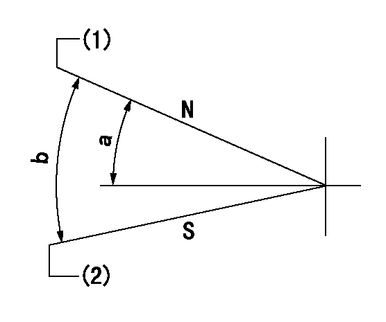
N:Pump normal
S:Stop the pump.
(1)Rack position = aa
(2)Rack position bb
----------
aa=18.2+0.3mm bb=1mm
----------
a=23.5deg+-5deg b=33.5deg+-5deg
----------
aa=18.2+0.3mm bb=1mm
----------
a=23.5deg+-5deg b=33.5deg+-5deg
0000000901

(1)Pump vertical direction
(2)Coupling's key groove position at No 1 cylinder's beginning of injection
(3)B.T.D.C.: aa
(4)-
----------
aa=16deg
----------
a=(5deg)
----------
aa=16deg
----------
a=(5deg)
Stop lever angle

(Rs) rack sensor specifications
(C/U) control unit part number
(V) Rack sensor output voltage
(R) Rack position (mm)
1. Confirming governor output characteristics (rack 19 mm, span 6 mm)
(1)When the output voltages of the rack sensor are V1 and V2, check that the rack positions R1 and R2 in the table above are satisfied.
----------
----------
----------
----------
Information:
Install the pump cover onto the pump housing. Tighten the four middle bolts. Then, tighten the end bolts in a crisscross pattern. Tighten the bolts to a torque of 10.2 N m (90 lb in).Note: Make sure that the gasket is in place between the housing and the cover.
Repeat Step 1 and Step 2 in order to confirm the electrical connection for the pump coil was not damaged during the removal of the pump cover.
Install the oil inlet line adapter, inlet line, and harness connector to the pump.Note: After the HEUI pump is replaced or reassembled, the engine must be cranked for an extended length of time to fill the pump with oil.Note: Clear any diagnostic or event codes that activated during the initial start-up.
If the engine would not start before inspecting for debris and no debris was found in the HEUI pump, return to Step D in the diagnostic flow chart.If the engine would start before inspecting for debris and no debris was found in the HEUI pump, return to Step L in the diagnostic flow chart.If the pump is to be replaced, complete the checklist form in Special Instruction, REHS5031 that is provided with the service replacement part and insert the completed form back into the box containing the part that is being returned. Proceed to the section of this instruction titled "Oil Rail Cleaning Procedure" for the correct engine size that is being serviced.Oil Rail Cleaning Procedure For the C7 Engine
Illustration 12 g02702636
C7 Cylinder Head
Illustration 13 g02708256
The oil and fuel passages are the same for both the C7 and C9.
(6) Oil Rail for a HEUI fuel system
(7) Oil passage to injector bore
(8) Fuel passage
(9) Injector bore Note: Contain any oil and cleaner that will flow from the cylinder and the lines during the following process. Properly dispose of the oil and contaminated cleaner when work is complete.
Remove fuel injectors. Refer to Disassembly and Assembly for specific machine.
Install six plugs 9U-7080 Tapered Cap/Plug into the lower injector bores. The plugs will prevent oil, cleaners, and debris from entering the cylinders.
Remove the plugs from the front and rear of the cylinder head main oil gallery
Remove the pressure sensor from the cylinder head. Protect the sensor.
Clean out the two rail drain holes by removing their plugs and using the brake cleaner and long squirting straw to flush these passages to the oil rail.
Using the solvent gun with and without the