Information injection-pump assembly
BOSCH
9 400 617 514
9400617514
ZEXEL
106681-4450
1066814450

Rating:
Cross reference number
BOSCH
9 400 617 514
9400617514
ZEXEL
106681-4450
1066814450
Zexel num
Bosch num
Firm num
Name
106681-4450
9 400 617 514
INJECTION-PUMP ASSEMBLY
6CZ-GT 14CA INJECTION PUMP ASSY PE6P,6PD PE
6CZ-GT 14CA INJECTION PUMP ASSY PE6P,6PD PE
9 400 617 514
12788151980 YANMAR
INJECTION-PUMP ASSEMBLY
6CZ-GT K 14CA INJECTION PUMP ASSY PE6P,6PD PE
6CZ-GT K 14CA INJECTION PUMP ASSY PE6P,6PD PE
Calibration Data:
Adjustment conditions
Test oil
1404 Test oil ISO4113 or {SAEJ967d}
1404 Test oil ISO4113 or {SAEJ967d}
Test oil temperature
degC
40
40
45
Nozzle and nozzle holder
105780-8130
Bosch type code
EFEP215A
Nozzle
105780-0050
Bosch type code
DN6TD119NP1T
Nozzle holder
105780-2090
Bosch type code
EFEP215
Opening pressure
MPa
17.2
Opening pressure
kgf/cm2
175
Injection pipe
Outer diameter - inner diameter - length (mm) mm 8-4-1000
Outer diameter - inner diameter - length (mm) mm 8-4-1000
Overflow valve
131425-1620
Overflow valve opening pressure
kPa
255
221
289
Overflow valve opening pressure
kgf/cm2
2.6
2.25
2.95
Tester oil delivery pressure
kPa
255
255
255
Tester oil delivery pressure
kgf/cm2
2.6
2.6
2.6
Direction of rotation (viewed from drive side)
Left L
Left L
Injection timing adjustment
Direction of rotation (viewed from drive side)
Left L
Left L
Injection order
1-5-3-6-
2-4
Pre-stroke
mm
3.3
3.25
3.35
Beginning of injection position
Drive side NO.1
Drive side NO.1
Difference between angles 1
Cal 1-5 deg. 60 59.5 60.5
Cal 1-5 deg. 60 59.5 60.5
Difference between angles 2
Cal 1-3 deg. 120 119.5 120.5
Cal 1-3 deg. 120 119.5 120.5
Difference between angles 3
Cal 1-6 deg. 180 179.5 180.5
Cal 1-6 deg. 180 179.5 180.5
Difference between angles 4
Cyl.1-2 deg. 240 239.5 240.5
Cyl.1-2 deg. 240 239.5 240.5
Difference between angles 5
Cal 1-4 deg. 300 299.5 300.5
Cal 1-4 deg. 300 299.5 300.5
Injection quantity adjustment
Adjusting point
A
Rack position
14.9
Pump speed
r/min
1150
1150
1150
Each cylinder's injection qty
mm3/st.
424
411.3
436.7
Basic
*
Fixing the lever
*
Boost pressure
kPa
112
112
Boost pressure
mmHg
840
840
Injection quantity adjustment_02
Adjusting point
B
Rack position
7.2+-0.5
Pump speed
r/min
250
250
250
Each cylinder's injection qty
mm3/st.
21.5
18.3
24.7
Fixing the rack
*
Boost pressure
kPa
0
0
0
Boost pressure
mmHg
0
0
0
Injection quantity adjustment_03
Adjusting point
C
Rack position
15.1++
Pump speed
r/min
100
100
100
Average injection quantity
mm3/st.
460
450
470
Fixing the lever
*
Boost pressure
kPa
0
0
0
Boost pressure
mmHg
0
0
0
Rack limit
*
Boost compensator adjustment
Pump speed
r/min
500
500
500
Rack position
R1-2.8
Boost pressure
kPa
52
49.3
54.7
Boost pressure
mmHg
390
370
410
Boost compensator adjustment_02
Pump speed
r/min
500
500
500
Rack position
R1(14.9)
Boost pressure
kPa
98.6
91.9
105.3
Boost pressure
mmHg
740
690
790
Timer adjustment
Pump speed
r/min
480--
Advance angle
deg.
0
0
0
Remarks
Start
Start
Timer adjustment_02
Pump speed
r/min
430
Advance angle
deg.
0.5
Timer adjustment_03
Pump speed
r/min
600
Advance angle
deg.
1
0.5
1.5
Remarks
Finish
Finish
Test data Ex:
Governor adjustment
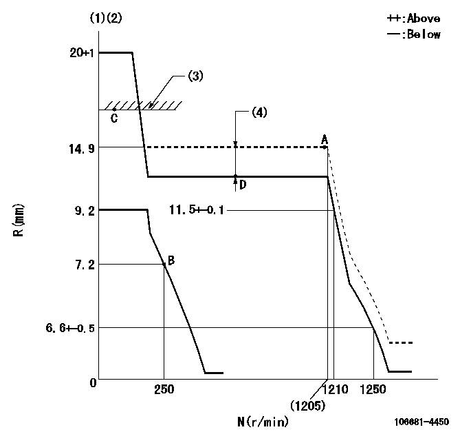
N:Pump speed
R:Rack position (mm)
(1)Target notch: K
(2)Tolerance for racks not indicated: +-0.05mm.
(3)RACK LIMIT
(4)Boost compensator stroke: BCL
----------
K=6 BCL=2.8+-0.1mm
----------
----------
K=6 BCL=2.8+-0.1mm
----------
Speed control lever angle
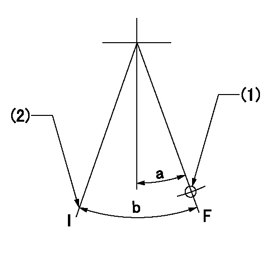
F:Full speed
I:Idle
(1)Use the hole at R = aa
(2)Stopper bolt setting
----------
aa=100mm
----------
a=12deg+-5deg b=37deg+-5deg
----------
aa=100mm
----------
a=12deg+-5deg b=37deg+-5deg
Stop lever angle
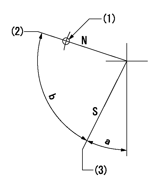
N:Pump normal
S:Stop the pump.
(1)Use the hole at R = aa
(2)Normal
(3)Rack position bb, pump speed cc (seal at delivery)
----------
aa=20mm bb=1-0.5mm cc=0r/min
----------
a=37deg+-5deg b=(73deg)
----------
aa=20mm bb=1-0.5mm cc=0r/min
----------
a=37deg+-5deg b=(73deg)
Timing setting

(1)Pump vertical direction
(2)Coupling's key groove position at No 1 cylinder's beginning of injection
(3)-
(4)-
----------
----------
a=(50deg)
----------
----------
a=(50deg)
Information:
Do not operate or work on this product unless you have read and understood the instruction and warnings in the relevant Operation and Maintenance Manuals and relevant service literature. Failure to follow the instructions or heed the warnings could result in injury or death. Proper care is your responsibility.
The following changes are adaptable to the products within the listed serial numbers, and are effective with all products after the listed serial numbers.
Illustration 1 g06489757When replacing or installing new fuel injectors, apply Nyogel® 760G lubricant on the terminals of the injector solenoid as shown in Illustration 1.The Nyogel® 760G lubricant can be ordered at the address below.https://www.nyelubricants.com/nyogel
Have questions with 106681-4450?
Group cross 106681-4450 ZEXEL
Mitsubishi-Heav
Mitsubishi-Heav
106681-4450
9 400 617 514
INJECTION-PUMP ASSEMBLY
6CZ-GT
6CZ-GT