Information injection-pump assembly
ZEXEL
106681-4440
1066814440
MITSUBISHI-HEAV
35A6500210
35a6500210

Rating:
Cross reference number
ZEXEL
106681-4440
1066814440
MITSUBISHI-HEAV
35A6500210
35a6500210
Zexel num
Bosch num
Firm num
Name
Calibration Data:
Adjustment conditions
Test oil
1404 Test oil ISO4113 or {SAEJ967d}
1404 Test oil ISO4113 or {SAEJ967d}
Test oil temperature
degC
40
40
45
Nozzle and nozzle holder
105780-8130
Bosch type code
EFEP215A
Nozzle
105780-0050
Bosch type code
DN6TD119NP1T
Nozzle holder
105780-2090
Bosch type code
EFEP215
Opening pressure
MPa
17.2
Opening pressure
kgf/cm2
175
Injection pipe
Outer diameter - inner diameter - length (mm) mm 8-4-1000
Outer diameter - inner diameter - length (mm) mm 8-4-1000
Overflow valve
131424-3240
Overflow valve opening pressure
kPa
255
255
255
Overflow valve opening pressure
kgf/cm2
2.6
2.6
2.6
Tester oil delivery pressure
kPa
255
255
255
Tester oil delivery pressure
kgf/cm2
2.6
2.6
2.6
Direction of rotation (viewed from drive side)
Left L
Left L
Injection timing adjustment
Direction of rotation (viewed from drive side)
Left L
Left L
Injection order
1-5-3-6-
2-4
Pre-stroke
mm
2.8
2.75
2.85
Beginning of injection position
Governor side NO.1
Governor side NO.1
Difference between angles 1
Cal 1-5 deg. 60 59.5 60.5
Cal 1-5 deg. 60 59.5 60.5
Difference between angles 2
Cal 1-3 deg. 120 119.5 120.5
Cal 1-3 deg. 120 119.5 120.5
Difference between angles 3
Cal 1-6 deg. 180 179.5 180.5
Cal 1-6 deg. 180 179.5 180.5
Difference between angles 4
Cyl.1-2 deg. 240 239.5 240.5
Cyl.1-2 deg. 240 239.5 240.5
Difference between angles 5
Cal 1-4 deg. 300 299.5 300.5
Cal 1-4 deg. 300 299.5 300.5
Injection quantity adjustment
Adjusting point
A
Rack position
13
Pump speed
r/min
900
900
900
Average injection quantity
mm3/st.
377
367
387
Max. variation between cylinders
%
0
-3
3
Basic
*
Fixing the lever
*
Boost pressure
kPa
61.3
61.3
Boost pressure
mmHg
460
460
Injection quantity adjustment_02
Adjusting point
C
Rack position
7.2+-0.5
Pump speed
r/min
350
350
350
Average injection quantity
mm3/st.
20
17
23
Max. variation between cylinders
%
0
-10
10
Fixing the rack
*
Boost pressure
kPa
0
0
0
Boost pressure
mmHg
0
0
0
Injection quantity adjustment_03
Adjusting point
E
Rack position
-
Pump speed
r/min
100
100
100
Average injection quantity
mm3/st.
370
350
390
Fixing the lever
*
Boost pressure
kPa
0
0
0
Boost pressure
mmHg
0
0
0
Boost compensator adjustment
Pump speed
r/min
575
575
575
Rack position
R1-1.5
Boost pressure
kPa
30.7
28
33.4
Boost pressure
mmHg
230
210
250
Boost compensator adjustment_02
Pump speed
r/min
575
575
575
Rack position
R1(13)
Boost pressure
kPa
48
41.3
54.7
Boost pressure
mmHg
360
310
410
Timer adjustment
Pump speed
r/min
470--
Advance angle
deg.
0
0
0
Remarks
Start
Start
Timer adjustment_02
Pump speed
r/min
420
Advance angle
deg.
0.5
Timer adjustment_03
Pump speed
r/min
650
Advance angle
deg.
2
1.5
2.5
Remarks
Finish
Finish
Test data Ex:
Governor adjustment
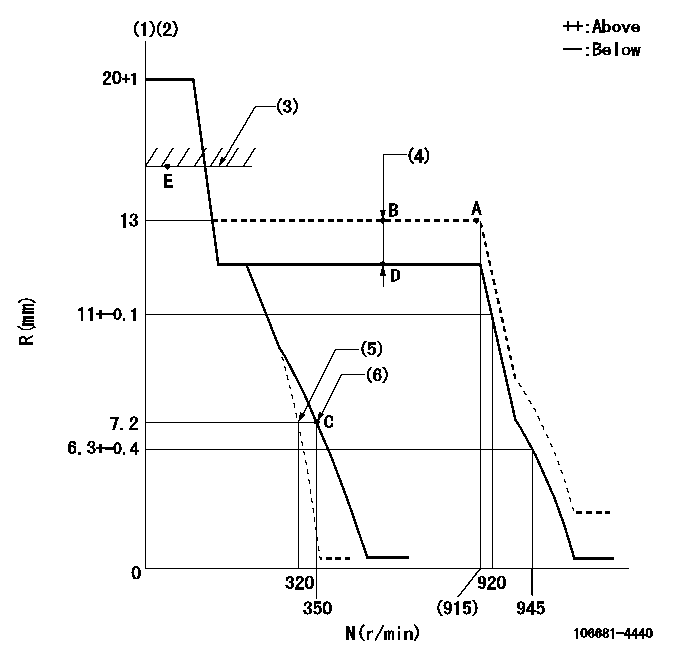
N:Pump speed
R:Rack position (mm)
(1)Target notch: K
(2)Tolerance for racks not indicated: +-0.05mm.
(3)RACK LIMIT
(4)Boost compensator stroke: BCL
(5)Main spring setting
(6)Set idle sub-spring
----------
K=8 BCL=1.5+-0.1mm
----------
----------
K=8 BCL=1.5+-0.1mm
----------
Speed control lever angle
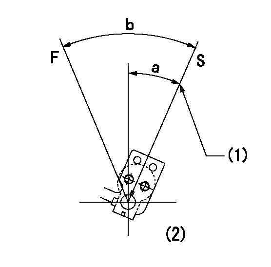
F:Full speed
I:Idle
(1)Stopper bolt setting
(2)At the center of the lever key groove
----------
----------
a=26deg+-5deg b=26deg+-5deg
----------
----------
a=26deg+-5deg b=26deg+-5deg
Stop lever angle
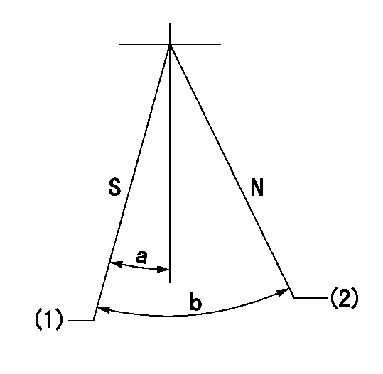
N:Pump normal
S:Stop the pump.
(1)Pump speed aa, rack position bb
(2)Normal
----------
aa=0r/min bb=1-0.5mm
----------
a=33deg+-5deg b=(73deg)
----------
aa=0r/min bb=1-0.5mm
----------
a=33deg+-5deg b=(73deg)
Timing setting

(1)Pump vertical direction
(2)Coupling's key groove position at No 1 cylinder's beginning of injection
(3)-
(4)-
----------
----------
a=(20deg)
----------
----------
a=(20deg)
Information:
start by: a) remove oil pump 1. Check each main bearing cap (1) for its location on the engine. Each cap has a number which gives its location of that cap.2. Remove the nuts that hold the main bearing cap in position and remove bearing cap (1) from the engine. Remove the lower half of the main bearings from the cap. 3. Turn the crankshaft until tool (A) can be installed in oil hole of the crankshaft. Turn the crankshaft in the direction which will push the upper main bearing out, tab end first.
If the crankshaft is turned in the wrong direction, the tab of the bearing will be pushed between the crankshaft and the cylinder block. This will cause damage to the crankshaft and block.
4. Put clean engine oil on the lower bearings. Install lower bearings in the bearing caps.5. Put clean engine oil on the upper bearings. Install upper bearings in the cylinder block with tool (A). Be sure the tab on the back of the bearings fits in the grooves of the caps and cylinder block. When the bearing clearance is checked the crankshaft will have to be lifted up against the upper halves of the main bearings and held to get a measurement with wire (2). The wire will not hold the weight of the crankshaft.6. Check the bearing clearance with wire (2) as follows: a) Put a piece of 5B1161 Wire (2) in position across the lower half of the main bearing.b) Install the cap, bearing and wire (2) in the block. Make sure the bearing location tangs are on the same side of the block.c) Tighten the nuts that hold the main bearing cap to a torque of 75 5 lb. ft. (100 7 N m) plus 120° 5°.7. Remove the main bearing cap and measure thickness (bearing clearance). The bearing clearance must be .0035 to .0066 in. (0.089 to 0.168 mm) and must not be more than .010 in. (0.25 mm). 8. If bearing clearance is correct, install bearing and cap on the block. Put engine oil on crankshaft and main bearing cap. Tighten nuts to a torque of 75 5 lb. ft. (100 7 N m) plus 120° 5°.end by: a) install oil pump