Information injection-pump assembly
BOSCH
9 400 617 513
9400617513
ZEXEL
106681-4430
1066814430

Rating:
Cross reference number
BOSCH
9 400 617 513
9400617513
ZEXEL
106681-4430
1066814430
Zexel num
Bosch num
Firm num
Name
Calibration Data:
Adjustment conditions
Test oil
1404 Test oil ISO4113 or {SAEJ967d}
1404 Test oil ISO4113 or {SAEJ967d}
Test oil temperature
degC
40
40
45
Nozzle and nozzle holder
105780-8130
Bosch type code
EFEP215A
Nozzle
105780-0050
Bosch type code
DN6TD119NP1T
Nozzle holder
105780-2090
Bosch type code
EFEP215
Opening pressure
MPa
17.2
Opening pressure
kgf/cm2
175
Injection pipe
Outer diameter - inner diameter - length (mm) mm 8-4-1000
Outer diameter - inner diameter - length (mm) mm 8-4-1000
Overflow valve
131424-3420
Overflow valve opening pressure
kPa
255
221
289
Overflow valve opening pressure
kgf/cm2
2.6
2.25
2.95
Tester oil delivery pressure
kPa
255
255
255
Tester oil delivery pressure
kgf/cm2
2.6
2.6
2.6
Direction of rotation (viewed from drive side)
Left L
Left L
Injection timing adjustment
Direction of rotation (viewed from drive side)
Left L
Left L
Injection order
1-5-3-6-
2-4
Pre-stroke
mm
2.8
2.75
2.85
Rack position
Point A R=A
Point A R=A
Beginning of injection position
Governor side NO.1
Governor side NO.1
Difference between angles 1
Cal 1-5 deg. 60 59.5 60.5
Cal 1-5 deg. 60 59.5 60.5
Difference between angles 2
Cal 1-3 deg. 120 119.5 120.5
Cal 1-3 deg. 120 119.5 120.5
Difference between angles 3
Cal 1-6 deg. 180 179.5 180.5
Cal 1-6 deg. 180 179.5 180.5
Difference between angles 4
Cyl.1-2 deg. 240 239.5 240.5
Cyl.1-2 deg. 240 239.5 240.5
Difference between angles 5
Cal 1-4 deg. 300 299.5 300.5
Cal 1-4 deg. 300 299.5 300.5
Injection quantity adjustment
Adjusting point
A
Rack position
11.1
Pump speed
r/min
975
975
975
Average injection quantity
mm3/st.
310
301
319
Max. variation between cylinders
%
0
-3
3
Basic
*
Fixing the lever
*
Boost pressure
kPa
160
160
Boost pressure
mmHg
1200
1200
Injection quantity adjustment_02
Adjusting point
C
Rack position
6.2+-0.5
Pump speed
r/min
365
365
365
Average injection quantity
mm3/st.
19.5
16.5
22.5
Max. variation between cylinders
%
0
-10
10
Fixing the rack
*
Boost pressure
kPa
0
0
0
Boost pressure
mmHg
0
0
0
Injection quantity adjustment_03
Adjusting point
F
Rack position
-
Pump speed
r/min
1200
1200
1200
Average injection quantity
mm3/st.
0
0
0
Fixing the lever
*
Boost pressure
kPa
0
0
0
Boost pressure
mmHg
0
0
0
Boost compensator adjustment
Pump speed
r/min
500
500
500
Rack position
R1-2.75
Boost pressure
kPa
73.3
70.6
76
Boost pressure
mmHg
550
530
570
Boost compensator adjustment_02
Pump speed
r/min
500
500
500
Rack position
R1(12)
Boost pressure
kPa
147
140.3
153.7
Boost pressure
mmHg
1100
1050
1150
Timer adjustment
Pump speed
r/min
(N1+50)-
-
Advance angle
deg.
0
0
0
Remarks
Start
Start
Timer adjustment_02
Pump speed
r/min
N1
Advance angle
deg.
0
0
0
Remarks
Measure the actual speed.
Measure the actual speed.
Timer adjustment_03
Pump speed
r/min
N2
Advance angle
deg.
4
3.5
4.5
Remarks
Measure the actual speed, stop
Measure the actual speed, stop
Test data Ex:
Governor adjustment
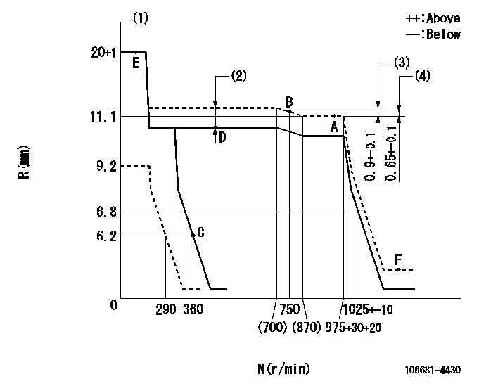
N:Pump speed
R:Rack position (mm)
(1)Target notch: K
(2)Boost compensator stroke: BCL
(3)Rack difference between N = N1 and N = N2
(4)Rack difference between N = N3 and N = N4
----------
K=5?`25 BCL=2.75+-0.1mm N1=975r/min N2=500r/min N3=975r/min N4=750r/min
----------
----------
K=5?`25 BCL=2.75+-0.1mm N1=975r/min N2=500r/min N3=975r/min N4=750r/min
----------
Speed control lever angle
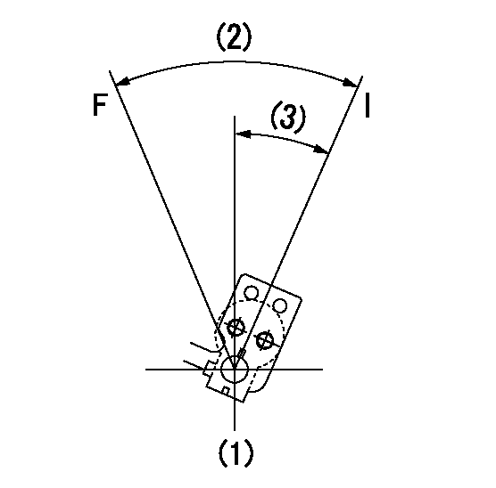
F:Full speed
I:Idle
(1)At the center of the lever key groove
(2)Actual measurement
(3)Actual measurement
----------
----------
----------
----------
Stop lever angle
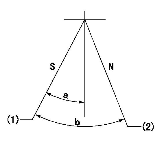
N:Pump normal
S:Stop the pump.
(1)Pump speed aa, rack position bb
(2)Normal
----------
aa=0r/min bb=1-0.5mm
----------
a=33deg+-5deg b=(73deg)
----------
aa=0r/min bb=1-0.5mm
----------
a=33deg+-5deg b=(73deg)
Timing setting
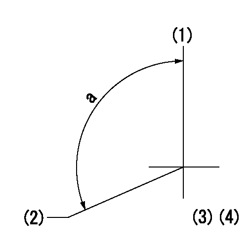
(1)Pump vertical direction
(2)Coupling's key groove position at No 1 cylinder's beginning of injection
(3)-
(4)-
----------
----------
a=(110deg)
----------
----------
a=(110deg)
Information:
start by: a) remove flywheel housingb) remove crankshaft rear seal 1. Turn the crankshaft until the access holes in gears (1), (2) and (3) are in alignment with the nuts or bolts that hold the thrust washers to the timing gear plate. Turn the crankshaft more than one time if necessary to remove all of the nuts and bolts from the thrust washers. Do not remove any of the gears at this time.2. Turn the crankshaft to top center of compression stroke for No.1 piston. See LOCATING TOP CENTER FOR NO.1 PISTON in TESTING AND ADJUSTING.3. Install a 3/8"-16 NC eyebolt in drive shaft (6) and remove it from camshaft drive gear.
Do not turn crankshaft after drive shaft (6) or any of the gears are removed or damage to the pistons and valves will be the result.
4. Remove bolts (4), locks (5) and the hub from gear (7). 5. Remove the bolts, lock and washer to remove air compressor drive gear (8) from the timing gear plate. 6. Use tooling (A) and a press to remove the bearing from gear (8) as shown. 7. Remove gears (1), (2) and (3) and the thrust washers from the timing gear plate. 8. Use tooling (A) and a press to remove the bearings from gears (1), (2) and (3) as shown. 9. Turn gear (7) to make an alignment of the access holes in the gear with bolts (9). Remove the bolts, gear (7) and thrust washer from the timing gear plate. 10. Use tooling (A) and a press to remove the bearing from gear (7) as shown.Install Timing Gears
1. Use tooling (A) and a press to install the bearing in gear (1), until the bearing is even with the surface of the gear. 2. Install gear (1) and thrust washer (2) on the timing gear plate and tighten the bolts and locks to hold the thrust washer. 3. Use tooling (A) and a press to install the bearing in gear (3), until the bearing is even with the surface of the gear. 4. Use tooling (A) and a press to install the bearing in gear (4), until the bearing is even with the top surface of the gear as shown. 5. Put the bearing in position in compressor drive gear (5). Make sure that the reliefs in the bearing are in alignment with the reliefs in the gear. Use tooling (A) and a press to install the bearing even with the surface of gear (5) as shown. 6. Install the bearing in gear (6) with tooling (A) and a press until it is even with the surface of the gear.7. Make an alignment of the "V" mark on gear (3) with the "V" mark on the crankshaft gear and install gear (3) and the thrust washer on the timing gear plate. Tighten the bolts and lock to hold the thrust washer. 8. Make an alignment of the "V" mark on gear (4) with the "V" mark on gear (3) and