Information injection-pump assembly
ZEXEL
106681-4420
1066814420
MITSUBISHI-HEAV
34A6500530
34a6500530

Rating:
Cross reference number
ZEXEL
106681-4420
1066814420
MITSUBISHI-HEAV
34A6500530
34a6500530
Zexel num
Bosch num
Firm num
Name
Calibration Data:
Adjustment conditions
Test oil
1404 Test oil ISO4113 or {SAEJ967d}
1404 Test oil ISO4113 or {SAEJ967d}
Test oil temperature
degC
40
40
45
Nozzle and nozzle holder
105780-8130
Bosch type code
EFEP215A
Nozzle
105780-0050
Bosch type code
DN6TD119NP1T
Nozzle holder
105780-2090
Bosch type code
EFEP215
Opening pressure
MPa
17.2
Opening pressure
kgf/cm2
175
Injection pipe
Outer diameter - inner diameter - length (mm) mm 8-4-1000
Outer diameter - inner diameter - length (mm) mm 8-4-1000
Overflow valve
131424-3420
Overflow valve opening pressure
kPa
255
221
289
Overflow valve opening pressure
kgf/cm2
2.6
2.25
2.95
Tester oil delivery pressure
kPa
255
255
255
Tester oil delivery pressure
kgf/cm2
2.6
2.6
2.6
Direction of rotation (viewed from drive side)
Left L
Left L
Injection timing adjustment
Direction of rotation (viewed from drive side)
Left L
Left L
Injection order
1-5-3-6-
2-4
Pre-stroke
mm
2.8
2.75
2.85
Beginning of injection position
Governor side NO.1
Governor side NO.1
Difference between angles 1
Cal 1-5 deg. 60 59.5 60.5
Cal 1-5 deg. 60 59.5 60.5
Difference between angles 2
Cal 1-3 deg. 120 119.5 120.5
Cal 1-3 deg. 120 119.5 120.5
Difference between angles 3
Cal 1-6 deg. 180 179.5 180.5
Cal 1-6 deg. 180 179.5 180.5
Difference between angles 4
Cyl.1-2 deg. 240 239.5 240.5
Cyl.1-2 deg. 240 239.5 240.5
Difference between angles 5
Cal 1-4 deg. 300 299.5 300.5
Cal 1-4 deg. 300 299.5 300.5
Injection quantity adjustment
Adjusting point
A
Rack position
13
Pump speed
r/min
900
900
900
Average injection quantity
mm3/st.
368
359
377
Max. variation between cylinders
%
0
-3
3
Basic
*
Fixing the lever
*
Boost pressure
kPa
61.3
61.3
Boost pressure
mmHg
460
460
Injection quantity adjustment_02
Adjusting point
C
Rack position
6.8+-0.5
Pump speed
r/min
350
350
350
Average injection quantity
mm3/st.
28.5
25.5
31.5
Max. variation between cylinders
%
0
-10
10
Fixing the rack
*
Boost pressure
kPa
0
0
0
Boost pressure
mmHg
0
0
0
Injection quantity adjustment_03
Adjusting point
E
Rack position
13.2++
Pump speed
r/min
100
100
100
Average injection quantity
mm3/st.
440
420
460
Fixing the lever
*
Boost pressure
kPa
0
0
0
Boost pressure
mmHg
0
0
0
Injection quantity adjustment_04
Adjusting point
F
Rack position
4.5--
Pump speed
r/min
1050
1050
1050
Average injection quantity
mm3/st.
0
0
0
Fixing the lever
*
Boost pressure
kPa
61.3
61.3
Boost pressure
mmHg
460
460
Boost compensator adjustment
Pump speed
r/min
575
575
575
Rack position
R1-1.5
Boost pressure
kPa
30.7
28
33.4
Boost pressure
mmHg
230
210
250
Boost compensator adjustment_02
Pump speed
r/min
575
575
575
Rack position
R1(13)
Boost pressure
kPa
48
41.3
54.7
Boost pressure
mmHg
360
310
410
Timer adjustment
Pump speed
r/min
(N1+50)-
-
Advance angle
deg.
0
0
0
Remarks
Start
Start
Timer adjustment_02
Pump speed
r/min
N1
Advance angle
deg.
0.5
Remarks
Measure the actual speed.
Measure the actual speed.
Timer adjustment_03
Pump speed
r/min
N2
Advance angle
deg.
4
3.5
4.5
Remarks
Measure the actual speed, stop
Measure the actual speed, stop
Test data Ex:
Governor adjustment
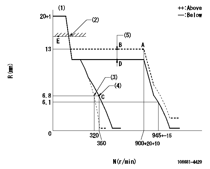
N:Pump speed
R:Rack position (mm)
(1)Target notch: K
(2)RACK LIMIT
(3)Main spring setting
(4)Set idle sub-spring
(5)Boost compensator stroke: BCL
----------
K=5?`25 BCL=1.5+-0.1mm
----------
----------
K=5?`25 BCL=1.5+-0.1mm
----------
Speed control lever angle
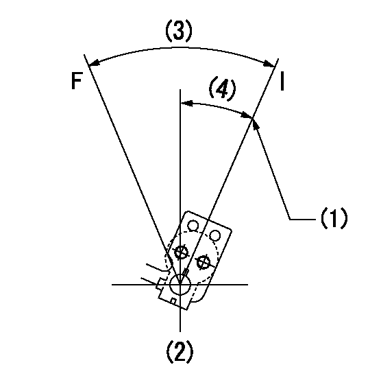
F:Full speed
I:Idle
(1)Stopper bolt setting
(2)At the center of the lever key groove
(3)Actual measurement
(4)Actual measurement
----------
----------
----------
----------
Stop lever angle
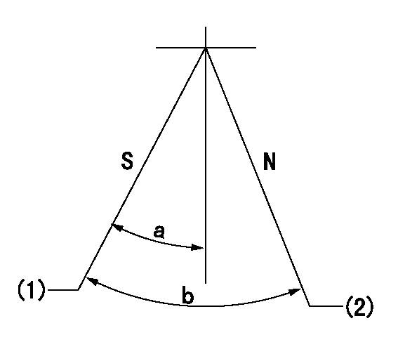
N:Pump normal
S:Stop the pump.
(1)Pump speed aa, rack position bb
(2)Normal
----------
aa=0r/min bb=1-0.5mm
----------
a=33deg+-5deg b=(73deg)
----------
aa=0r/min bb=1-0.5mm
----------
a=33deg+-5deg b=(73deg)
Timing setting

(1)Pump vertical direction
(2)Coupling's key groove position at No 1 cylinder's beginning of injection
(3)-
(4)-
----------
----------
a=(20deg)
----------
----------
a=(20deg)
Information:
1. Remove all of bolts (1) and bolts (2) and (3).2. Use two 3/8"-16 NC forcing screws and remove stator (4) from the flywheel housing. 3. If necessary remove the lip type seal from stator (4) with a hammer and punch. 4. Remove the six O-ring seals (6) from the flywheel housing.5. Remove rotor (5) from the crankshaft. 6. Remove the seal ring from carrier (8).7. If necessary remove carrier (8) and sleeve (7) from rotor (5). The carrier and sleeve will have damage after removal. Use new parts for replacement.Install BrakeSaver
1. If the carrier and sleeve were removed from the rotor, heat the new parts to a maximum temperature of 300° F (149° C). 2. Install carrier (2) on rotor (3).3. Put 7M7260 Liquid Gasket Material on the outside diameter (4) of rotor (3) and let it dry. Install sleeve (1) on rotor (3) as shown. 4. Install seal ring (5) in the carrier. 5. Install two 3/4"-16 NF guide bolts (6) a minimum of 5 in. long in the crankshaft.6. Make sure the O-ring seal is on rear face of the crankshaft seal carrier and install rotor (3) on the guide bolts with the marked bolt hole of the rotor in alignment with the marked hole of the crankshaft. 7. Use tool (A) and a press to install the seal in stator (7) as shown. 8. Install O-ring seal in position on stator (7). Install O-ring seals (8) in the flywheel housing.9. Put stator (7) in position on the flywheel housing. 10. Put 9S3263 Thread Lock on the threads of the bolts that hold the stator and install them. Tighten all of bolts (9) evenly to a torque of 40 5 lb. ft. (55 7 N m). Tighten bolts (10) and (11) to a torque of 90 10 lb. ft. (120 14 N m).end by: a) install flywheel
1. If the carrier and sleeve were removed from the rotor, heat the new parts to a maximum temperature of 300° F (149° C). 2. Install carrier (2) on rotor (3).3. Put 7M7260 Liquid Gasket Material on the outside diameter (4) of rotor (3) and let it dry. Install sleeve (1) on rotor (3) as shown. 4. Install seal ring (5) in the carrier. 5. Install two 3/4"-16 NF guide bolts (6) a minimum of 5 in. long in the crankshaft.6. Make sure the O-ring seal is on rear face of the crankshaft seal carrier and install rotor (3) on the guide bolts with the marked bolt hole of the rotor in alignment with the marked hole of the crankshaft. 7. Use tool (A) and a press to install the seal in stator (7) as shown. 8. Install O-ring seal in position on stator (7). Install O-ring seals (8) in the flywheel housing.9. Put stator (7) in position on the flywheel housing. 10. Put 9S3263 Thread Lock on the threads of the bolts that hold the stator and install them. Tighten all of bolts (9) evenly to a torque of 40 5 lb. ft. (55 7 N m). Tighten bolts (10) and (11) to a torque of 90 10 lb. ft. (120 14 N m).end by: a) install flywheel