Information injection-pump assembly
ZEXEL
106681-4410
1066814410
MITSUBISHI-HEAV
34A6550280
34a6550280
Rating:
Cross reference number
ZEXEL
106681-4410
1066814410
MITSUBISHI-HEAV
34A6550280
34a6550280
Zexel num
Bosch num
Firm num
Name
Calibration Data:
Adjustment conditions
Test oil
1404 Test oil ISO4113 or {SAEJ967d}
1404 Test oil ISO4113 or {SAEJ967d}
Test oil temperature
degC
40
40
45
Nozzle and nozzle holder
105780-8130
Bosch type code
EFEP215A
Nozzle
105780-0050
Bosch type code
DN6TD119NP1T
Nozzle holder
105780-2090
Bosch type code
EFEP215
Opening pressure
MPa
17.2
Opening pressure
kgf/cm2
175
Injection pipe
Outer diameter - inner diameter - length (mm) mm 8-4-1000
Outer diameter - inner diameter - length (mm) mm 8-4-1000
Overflow valve
131424-3420
Overflow valve opening pressure
kPa
255
221
289
Overflow valve opening pressure
kgf/cm2
2.6
2.25
2.95
Tester oil delivery pressure
kPa
157
157
157
Tester oil delivery pressure
kgf/cm2
1.6
1.6
1.6
Direction of rotation (viewed from drive side)
Left L
Left L
Injection timing adjustment
Direction of rotation (viewed from drive side)
Left L
Left L
Injection order
1-5-3-6-
2-4
Pre-stroke
mm
2.8
2.75
2.85
Beginning of injection position
Governor side NO.1
Governor side NO.1
Difference between angles 1
Cal 1-5 deg. 60 59.5 60.5
Cal 1-5 deg. 60 59.5 60.5
Difference between angles 2
Cal 1-3 deg. 120 119.5 120.5
Cal 1-3 deg. 120 119.5 120.5
Difference between angles 3
Cal 1-6 deg. 180 179.5 180.5
Cal 1-6 deg. 180 179.5 180.5
Difference between angles 4
Cyl.1-2 deg. 240 239.5 240.5
Cyl.1-2 deg. 240 239.5 240.5
Difference between angles 5
Cal 1-4 deg. 300 299.5 300.5
Cal 1-4 deg. 300 299.5 300.5
Injection quantity adjustment
Adjusting point
A
Rack position
11.2
Pump speed
r/min
750
750
750
Average injection quantity
mm3/st.
303
294
312
Max. variation between cylinders
%
0
-3
3
Basic
*
Fixing the lever
*
Boost pressure
kPa
107
107
Boost pressure
mmHg
805
805
Remarks
Injection at all cylinders.
Injection at all cylinders.
Injection quantity adjustment_02
Adjusting point
C
Rack position
5.6+-0.5
Pump speed
r/min
350
350
350
Average injection quantity
mm3/st.
26
23
29
Max. variation between cylinders
%
0
-10
10
Fixing the rack
*
Boost pressure
kPa
0
0
0
Boost pressure
mmHg
0
0
0
Remarks
Injection only at cylinders 1, 3, 4 and 6.
Injection only at cylinders 1, 3, 4 and 6.
Injection quantity adjustment_03
Adjusting point
E
Rack position
11.4++
Pump speed
r/min
100
100
100
Average injection quantity
mm3/st.
260
260
280
Fixing the lever
*
Boost pressure
kPa
0
0
0
Boost pressure
mmHg
0
0
0
Rack limit
*
Boost compensator adjustment
Pump speed
r/min
500
500
500
Rack position
R1-2.5
Boost pressure
kPa
55.3
48.6
62
Boost pressure
mmHg
415
365
465
Boost compensator adjustment_02
Pump speed
r/min
500
500
500
Rack position
R1(11.2)
Boost pressure
kPa
98
95.3
100.7
Boost pressure
mmHg
735
715
755
Timer adjustment
Pump speed
r/min
450--
Advance angle
deg.
0
0
0
Remarks
Start
Start
Timer adjustment_02
Pump speed
r/min
400
Advance angle
deg.
0.5
Timer adjustment_03
Pump speed
r/min
700
Advance angle
deg.
4
3.5
4.5
Remarks
Finish
Finish
Test data Ex:
Governor adjustment
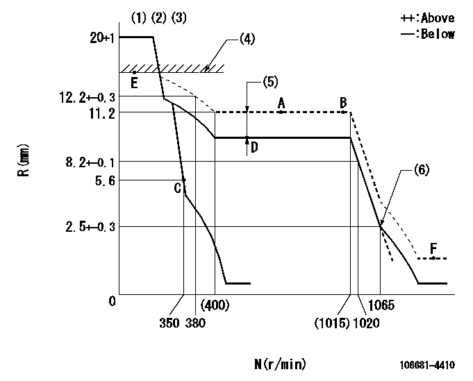
N:Pump speed
R:Rack position (mm)
(1)Target notch: K
(2)Tolerance for racks not indicated: +-0.05mm.
(3)The torque control spring does not operate.
(4)RACK LIMIT
(5)Boost compensator stroke: BCL
(6)Idle sub spring setting: L1.
----------
K=15 BCL=2.5+-0.1mm L1=2.5-0.5mm
----------
----------
K=15 BCL=2.5+-0.1mm L1=2.5-0.5mm
----------
Speed control lever angle
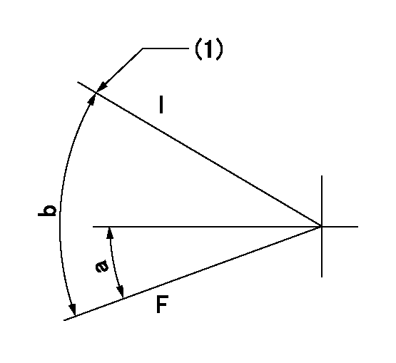
F:Full speed
I:Idle
(1)Stopper bolt setting
----------
----------
a=0deg+-5deg b=24deg+-5deg
----------
----------
a=0deg+-5deg b=24deg+-5deg
Stop lever angle
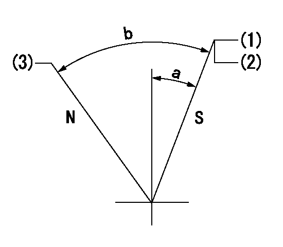
N:Pump normal
S:Stop the pump.
(1)Pump speed aa, rack position bb
(2)Seal at delivery.
(3)Normal
----------
aa=0r/min bb=3-0.5mm
----------
a=27deg+-5deg b=62.5deg+-5deg
----------
aa=0r/min bb=3-0.5mm
----------
a=27deg+-5deg b=62.5deg+-5deg
Timing setting

(1)Pump vertical direction
(2)Coupling's key groove position at No 1 cylinder's beginning of injection
(3)-
(4)-
----------
----------
a=(20deg)
----------
----------
a=(20deg)
Information:
3. Remove bearing caps (1) from the two connecting rods. Put pieces of rubber hose or tape on the threads of the connecting rod bolts as protection for the crankshaft. 4. Push the pistons up until the piston rings are clear of the cylinder liner. Remove pistons (2). Put identification on each piston as to its location for correct installation and alignment. Keep each cap with its connecting rod.
Do not turn the crankshaft while any of the connecting rods are in the engine without the caps installed.
5. Do Steps 1 through 4 for the remainder of the pistons.Install Pistons
1. Put clean engine oil on the piston rings, connecting rod bearings and cylinder liner. 2. Install piston into cylinder liner with tool (A). Push piston and rings through tool (A) with a hammer handle.3. Make a check of the connecting rod bearing clearance. See REMOVE AND INSTALL CONNECTING ROD BEARINGS. 4. Put clean engine oil on connecting rod cap and bearing. Install the cap (1) on the connecting rod. Tighten nuts to a torque of 50 5 lb. ft. (70 7 N m) plus 180°.5. Do Steps 1 through 4 for the remainder of the pistons.
As caps are installed, make sure that number identification on cap is on same side as number identification on rod.
end by: a) install cylinder head and spacer plateb) install oil pumpDisassemble Pistons
start by: a) remove pistons 1. Remove the retaining rings (2) for the piston pin.2. Remove piston pin (1) and remove piston from the connecting rod.3. Remove the piston rings using ring expander (A).Assemble Pistons
1. Use ring expander (A) to install the piston rings. The two compression rings have marks "UP-1" and "UP-2". The rings must be installed with the marks toward the top of the piston with "UP-1" being the top ring. Put the ring gaps in place 120° from each other.2. Put clean oil on the piston pin. Put the piston in place on the connecting rod. Install the piston pin and retaining rings. On some engines there can be a "V" mark (2) on the piston. This mark must be on the same side as the location number (1) on the connecting rod.end by: a) install pistons