Information injection-pump assembly
BOSCH
9 400 612 430
9400612430
ZEXEL
106681-4371
1066814371
YANMAR
12862451000
12862451000

Rating:
Service parts 106681-4371 INJECTION-PUMP ASSEMBLY:
1.
_
7.
COUPLING PLATE
8.
_
9.
_
10.
NOZZLE AND HOLDER ASSY
11.
Nozzle and Holder
12.
Open Pre:MPa(Kqf/cm2)
13.
NOZZLE-HOLDER
14.
NOZZLE
15.
NOZZLE SET
Include in #1:
106681-4371
as INJECTION-PUMP ASSEMBLY
Cross reference number
BOSCH
9 400 612 430
9400612430
ZEXEL
106681-4371
1066814371
YANMAR
12862451000
12862451000
Zexel num
Bosch num
Firm num
Name
106681-4371
9 400 612 430
12862451000 YANMAR
INJECTION-PUMP ASSEMBLY
6GHA-ET K 14CA INJECTION PUMP ASSY PE6P,6PD PE
6GHA-ET K 14CA INJECTION PUMP ASSY PE6P,6PD PE
Calibration Data:
Adjustment conditions
Test oil
1404 Test oil ISO4113 or {SAEJ967d}
1404 Test oil ISO4113 or {SAEJ967d}
Test oil temperature
degC
40
40
45
Nozzle and nozzle holder
105780-8130
Bosch type code
EFEP215A
Nozzle
105780-0050
Bosch type code
DN6TD119NP1T
Nozzle holder
105780-2090
Bosch type code
EFEP215
Opening pressure
MPa
17.2
Opening pressure
kgf/cm2
175
Injection pipe
Outer diameter - inner diameter - length (mm) mm 8-4-1000
Outer diameter - inner diameter - length (mm) mm 8-4-1000
Overflow valve
131425-1620
Overflow valve opening pressure
kPa
255
221
289
Overflow valve opening pressure
kgf/cm2
2.6
2.25
2.95
Tester oil delivery pressure
kPa
255
255
255
Tester oil delivery pressure
kgf/cm2
2.6
2.6
2.6
Direction of rotation (viewed from drive side)
Right R
Right R
Injection timing adjustment
Direction of rotation (viewed from drive side)
Right R
Right R
Injection order
1-4-2-6-
3-5
Pre-stroke
mm
4.1
4.05
4.15
Beginning of injection position
Drive side NO.1
Drive side NO.1
Difference between angles 1
Cal 1-4 deg. 60 59.5 60.5
Cal 1-4 deg. 60 59.5 60.5
Difference between angles 2
Cyl.1-2 deg. 120 119.5 120.5
Cyl.1-2 deg. 120 119.5 120.5
Difference between angles 3
Cal 1-6 deg. 180 179.5 180.5
Cal 1-6 deg. 180 179.5 180.5
Difference between angles 4
Cal 1-3 deg. 240 239.5 240.5
Cal 1-3 deg. 240 239.5 240.5
Difference between angles 5
Cal 1-5 deg. 300 299.5 300.5
Cal 1-5 deg. 300 299.5 300.5
Injection quantity adjustment
Adjusting point
A
Rack position
12.9
Pump speed
r/min
1175
1175
1175
Each cylinder's injection qty
mm3/st.
349
338.5
359.5
Basic
*
Fixing the lever
*
Boost pressure
kPa
98.6
98.6
Boost pressure
mmHg
740
740
Injection quantity adjustment_02
Adjusting point
B
Rack position
6.7+-0.5
Pump speed
r/min
225
225
225
Each cylinder's injection qty
mm3/st.
15
13.5
16.5
Fixing the rack
*
Boost pressure
kPa
0
0
0
Boost pressure
mmHg
0
0
0
Injection quantity adjustment_03
Adjusting point
C
Rack position
-
Pump speed
r/min
100
100
100
Average injection quantity
mm3/st.
285
285
305
Fixing the lever
*
Boost pressure
kPa
0
0
0
Boost pressure
mmHg
0
0
0
Rack limit
*
Boost compensator adjustment
Pump speed
r/min
500
500
500
Rack position
R1-0.85
Boost pressure
kPa
37.3
34.6
40
Boost pressure
mmHg
280
260
300
Boost compensator adjustment_02
Pump speed
r/min
500
500
500
Rack position
R1(12.9)
Boost pressure
kPa
85.3
85.3
85.3
Boost pressure
mmHg
640
640
640
Timer adjustment
Pump speed
r/min
400--
Advance angle
deg.
0
0
0
Remarks
Start
Start
Timer adjustment_02
Pump speed
r/min
350
Advance angle
deg.
0.5
Timer adjustment_03
Pump speed
r/min
520
Advance angle
deg.
1
0.7
1.3
Remarks
Finish
Finish
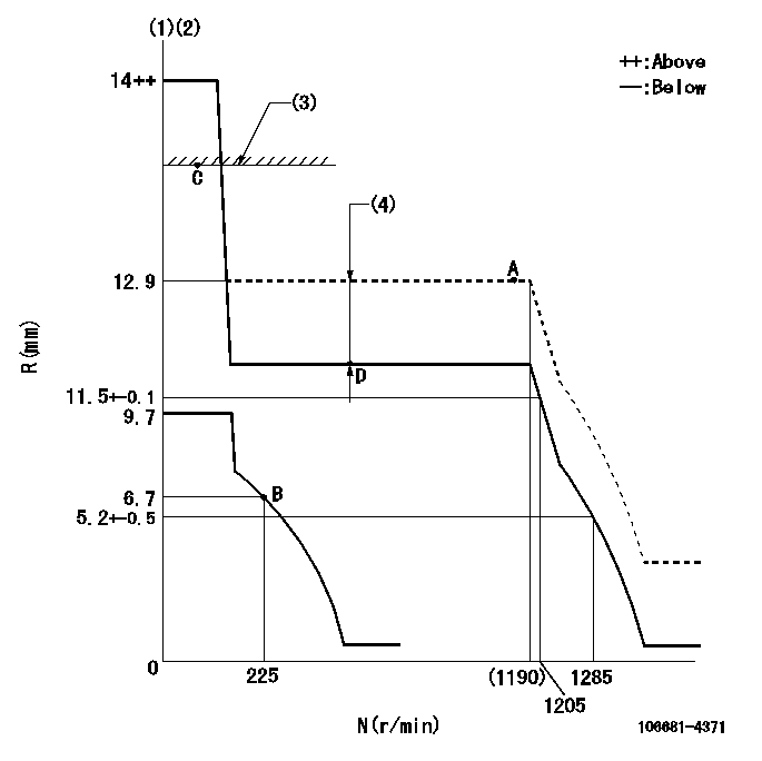
Test data Ex:
Governor adjustment

N:Pump speed
R:Rack position (mm)
(1)Target notch: K
(2)Tolerance for racks not indicated: +-0.05mm.
(3)RACK LIMIT
(4)Boost compensator stroke: BCL
----------
K=7 BCL=0.85+-0.1mm
----------
----------
K=7 BCL=0.85+-0.1mm
----------
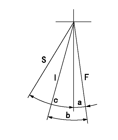
Speed control lever angle

F:Full speed
I:Idle
S:Stop
----------
----------
a=10deg+-5deg b=33deg+-5deg c=35deg+-3deg
----------
----------
a=10deg+-5deg b=33deg+-5deg c=35deg+-3deg
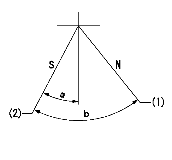
Stop lever angle

N:Pump normal
S:Stop the pump.
(1)Normal
(2)Pump speed aa, rack position bb
----------
aa=0r/min bb=1-0.5mm
----------
a=25deg+-5deg b=70deg+-5deg
----------
aa=0r/min bb=1-0.5mm
----------
a=25deg+-5deg b=70deg+-5deg
Timing setting

(1)Pump vertical direction
(2)Coupling's key groove position at No 1 cylinder's beginning of injection
(3)-
(4)-
----------
----------
a=(60deg)
----------
----------
a=(60deg)
Information:
8. Remove O-ring seal (10), the thrust washer and the bearing from the adapter with tool (A).9. Remove bolts (12) from the cover. Remove cover (11) and the gasket from the crankcase. 10. Bend down the lock on lock straps (13). Remove bolts (14) from the bearing caps.11. Put identification on the bearing caps for correct installation with the connecting rod. Remove the bearing caps. 12. Remove pistons (15) from the crankcase through the top of the cylinders.13. Remove crankshaft (16) from the crankcase. Remove the key from the crankshaft. 14. Remove end cover (17) from the crankcase. Remove the O-ring seal, the thrust washer and the bearing.15. Remove cover (18), the gasket and the strainer from the air inlet opening. 16. Remove inlet valves (20) from their guides (21). Remove the inlet valve guides from around the inlet valve seats.
Be careful not to cause damage to the inlet valve seats.
17. Remove (unloader) spring (19), spring saddle (22) and the spring seat from the housing with needle nose pliers. 18. Remove (unloader) plunger (24) and guides (25) from the housing. Remove the guides from the plungers to plungers.19. To remove (unloader) pistons (23) from the bore, put a cover over the inlet port, then blow air pressure in the governor mounting pad (unloader) port. 20. Remove lockpin (27) that holds rod pin (26) in the piston. Remove the pin from connecting rod (28). 21. Remove the piston rings from piston (30). Remove two compression rings (29), the oil ring and the expander ring with tool (B).22. Remove the bearings from the connecting rod and the connecting rod cap. 23. Remove the piston pin bushing with tool (C).24. Remove the small seal rings from both ends of the housing.25. Clean all the oil passages through the housing, the crankshaft, the end cover and the adapter. Assemble Air Compressor
1. Check (unloader) bore bushings (1) for damage and wear. If these bushings need replacement, remove the bushing by the use of a 1/8 in. (3.18 mm) pipe threaded tap. Then install a 1/8 in. (3.18 mm) pipe threaded rod and pull the bushing straight up and out.2. Check the cylinder bores in the crankcase housing for damages (scored or out of round). Measure the cylinder bore in several places. If the measurement difference is more than .001 in. (0.03 mm) or taper is more than .002 (0.05 mm), the cylinder bore must be made larger (rebored or honed oversize). See SPECIFICATIONS.3. Install seal rings (3) in both ends of the crankcase housing.4. Install the new (unloader) pistons in their bore.
Be careful not to cause damage to the O-ring seals or the spiral rings.
5. Put the unloader plungers in their guides. Install the plunger and guide as a unit (6) to the crankcase housing and on top of the pistons. Install the unloader spring seat in the crankcase housing. 6. Put saddle (4) in position between the unloader piston guides. Install (unloader) spring (8). Make sure it makes a seat on the
Have questions with 106681-4371?
Group cross 106681-4371 ZEXEL
Mitsubishi-Heav
Niigata-Urawa
Mitsubishi-Heav
Yanmar
Yanmar
Mitsubishi-Heav
Komatsu
Mitsubishi-Heav
Yanmar
106681-4371
9 400 612 430
12862451000
INJECTION-PUMP ASSEMBLY
6GHA-ET
6GHA-ET