Information injection-pump assembly
ZEXEL
106681-4370
1066814370

Rating:
Service parts 106681-4370 INJECTION-PUMP ASSEMBLY:
1.
_
7.
COUPLING PLATE
8.
_
9.
_
10.
NOZZLE AND HOLDER ASSY
11.
Nozzle and Holder
12.
Open Pre:MPa(Kqf/cm2)
25.5{260}
13.
NOZZLE-HOLDER
14.
NOZZLE
15.
NOZZLE SET
Include in #1:
106681-4370
as INJECTION-PUMP ASSEMBLY
Cross reference number
ZEXEL
106681-4370
1066814370
Zexel num
Bosch num
Firm num
Name
106681-4370
INJECTION-PUMP ASSEMBLY
14CA PE6P,6PD PE
14CA PE6P,6PD PE
Calibration Data:
Adjustment conditions
Test oil
1404 Test oil ISO4113 or {SAEJ967d}
1404 Test oil ISO4113 or {SAEJ967d}
Test oil temperature
degC
40
40
45
Nozzle and nozzle holder
105780-8130
Bosch type code
EFEP215A
Nozzle
105780-0050
Bosch type code
DN6TD119NP1T
Nozzle holder
105780-2090
Bosch type code
EFEP215
Opening pressure
MPa
17.2
Opening pressure
kgf/cm2
175
Injection pipe
Outer diameter - inner diameter - length (mm) mm 8-4-1000
Outer diameter - inner diameter - length (mm) mm 8-4-1000
Overflow valve
131424-7120
Overflow valve opening pressure
kPa
255
221
289
Overflow valve opening pressure
kgf/cm2
2.6
2.25
2.95
Tester oil delivery pressure
kPa
255
255
255
Tester oil delivery pressure
kgf/cm2
2.6
2.6
2.6
Direction of rotation (viewed from drive side)
Right R
Right R
Injection timing adjustment
Direction of rotation (viewed from drive side)
Right R
Right R
Injection order
1-4-2-6-
3-5
Pre-stroke
mm
4.1
4.05
4.15
Beginning of injection position
Drive side NO.1
Drive side NO.1
Difference between angles 1
Cal 1-4 deg. 60 59.5 60.5
Cal 1-4 deg. 60 59.5 60.5
Difference between angles 2
Cyl.1-2 deg. 120 119.5 120.5
Cyl.1-2 deg. 120 119.5 120.5
Difference between angles 3
Cal 1-6 deg. 180 179.5 180.5
Cal 1-6 deg. 180 179.5 180.5
Difference between angles 4
Cal 1-3 deg. 240 239.5 240.5
Cal 1-3 deg. 240 239.5 240.5
Difference between angles 5
Cal 1-5 deg. 300 299.5 300.5
Cal 1-5 deg. 300 299.5 300.5
Injection quantity adjustment
Adjusting point
A
Rack position
12.9
Pump speed
r/min
1175
1175
1175
Each cylinder's injection qty
mm3/st.
349
338.5
359.5
Basic
*
Fixing the lever
*
Boost pressure
kPa
98.6
98.6
Boost pressure
mmHg
740
740
Injection quantity adjustment_02
Adjusting point
B
Rack position
6.7+-0.5
Pump speed
r/min
225
225
225
Each cylinder's injection qty
mm3/st.
15
13.5
16.5
Fixing the rack
*
Boost pressure
kPa
0
0
0
Boost pressure
mmHg
0
0
0
Injection quantity adjustment_03
Adjusting point
C
Rack position
-
Pump speed
r/min
100
100
100
Average injection quantity
mm3/st.
285
285
305
Fixing the lever
*
Boost pressure
kPa
0
0
0
Boost pressure
mmHg
0
0
0
Rack limit
*
Boost compensator adjustment
Pump speed
r/min
500
500
500
Rack position
R1-0.85
Boost pressure
kPa
37.3
34.6
40
Boost pressure
mmHg
280
260
300
Boost compensator adjustment_02
Pump speed
r/min
500
500
500
Rack position
R1(12.9)
Boost pressure
kPa
85.3
85.3
85.3
Boost pressure
mmHg
640
640
640
Timer adjustment
Pump speed
r/min
400--
Advance angle
deg.
0
0
0
Remarks
Start
Start
Timer adjustment_02
Pump speed
r/min
350
Advance angle
deg.
0.5
Timer adjustment_03
Pump speed
r/min
520
Advance angle
deg.
1
0.7
1.3
Remarks
Finish
Finish
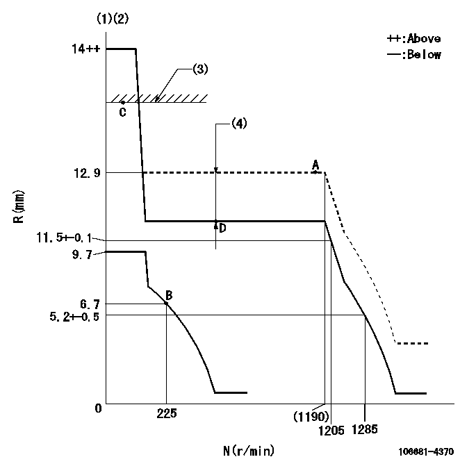
Test data Ex:
Governor adjustment

N:Pump speed
R:Rack position (mm)
(1)Target notch: K
(2)Tolerance for racks not indicated: +-0.05mm.
(3)RACK LIMIT
(4)Boost compensator stroke: BCL
----------
K=7 BCL=0.85+-0.1mm
----------
----------
K=7 BCL=0.85+-0.1mm
----------
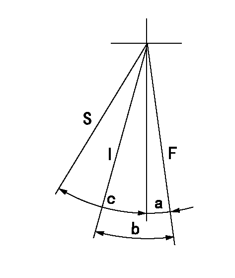
Speed control lever angle

F:Full speed
I:Idle
S:Stop
----------
----------
a=10deg+-5deg b=33deg+-5deg c=35deg+-3deg
----------
----------
a=10deg+-5deg b=33deg+-5deg c=35deg+-3deg
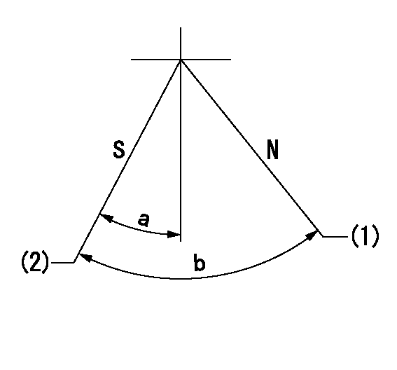
Stop lever angle

N:Pump normal
S:Stop the pump.
(1)Normal
(2)Pump speed aa, rack position bb
----------
aa=0r/min bb=1-0.5mm
----------
a=25deg+-5deg b=70deg+-5deg
----------
aa=0r/min bb=1-0.5mm
----------
a=25deg+-5deg b=70deg+-5deg
Timing setting

(1)Pump vertical direction
(2)Coupling's key groove position at No 1 cylinder's beginning of injection
(3)-
(4)-
----------
----------
a=(60deg)
----------
----------
a=(60deg)
Information:
3. Remove the water temperature regulator bypass water line (1).4. Disconnect the water inlet line from the bottom of the water pump. Disconnect the linkage for the governor.5. Disconnect the water supply line for the aftercooler.6. Install a 3/8"-16 NC forged eyebolt in the top of the water pump. Fasten a hoist to the water pump (2). Remove the bolts that hold the water pump to the engine and the engine oil cooler. Remove the water pump. Weight of the pump is 70 lb. (32 kg).Install Water Pump
1. Fasten a hoist to the water pump (1). Put the pump in position on the engine.2. Install the bolts that hold the water pump to the engine. Install the bolts (2) that fasten the water pump to the oil cooler.3. Install the water lines to the aftercooler and water temperature regulator housing.4. Install and adjust the drive belts on the water pump drive pulley. See LUBRICATION AND MAINTENANCE GUIDE.5. Fill the engine with oil and coolant to the correct levels.Disassemble Water
start by:a) remove water pump 1. Remove the pulley retaining nut and lock. Install tool (A) and remove the pulley. Remove the key.2. Remove the retainer and seal. Remove seal from retainer.3. Remove the cover retaining bolts and nuts. Remove the cover from the water pump housing. 4. Remove the impeller retaining nut. Remove the impeller (1) as the shaft is held and the impeller is turned clockwise.5. Remove the shaft assembly (2) from the housing. Remove the bearing assemblies and spacer from the shaft.6. Remove the carbon seal assembly and lip type seal from the housing.Assemble Water Pump
1. Use tool (A) to install the carbon seal assembly into water pump housing. Install the lip type seal in housing with lip of seal toward bearing assemblies. Put lubrication on the lip of seal with lubricant to be sealed.2. Install the bearing assemblies and spacer on the shaft. Install the shaft assembly in housing.3. Install the seal in the cage with lip of seal toward bearing assemblies. Put lubrication the lip of seal. Install the cage on the housing. 4. Install the pulley, lock and retaining nut. Tighten nut (2) to 100 10 lb.ft. (135.6 13.6 N m) and bend the lock.5. Install the impeller on shaft. Adjust impeller clearance (3) to .010 .005 in. (0.25 0.13 mm). Install the impeller retaining nut (1) and tighten to 50-55 lb. ft. (67.8-76.4 N m). After nut is tightened, hit the pulley end of shaft and check impeller clearance while impeller is turned.6. Install the water pump cover, retaining bolts and nuts.end by:a) install water pump
Have questions with 106681-4370?
Group cross 106681-4370 ZEXEL
Mitsubishi-Heav
Niigata-Urawa
Mitsubishi-Heav
Yanmar
Yanmar
Mitsubishi-Heav
Komatsu
Mitsubishi-Heav
106681-4370
INJECTION-PUMP ASSEMBLY