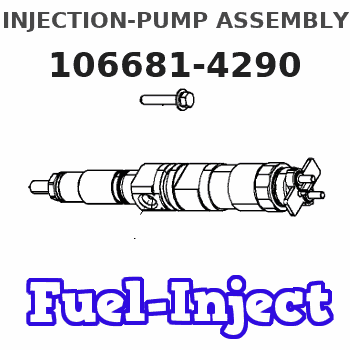
Information injection-pump assembly
ZEXEL
106681-4290
1066814290
Rating:
Service parts 106681-4290 INJECTION-PUMP ASSEMBLY:
1.
_
7.
COUPLING PLATE
8.
_
9.
_
11.
Nozzle and Holder
35A61-00040
12.
Open Pre:MPa(Kqf/cm2)
29.4{300}
15.
NOZZLE SET
Include in #1:
106681-4290
as INJECTION-PUMP ASSEMBLY
Cross reference number
ZEXEL
106681-4290
1066814290
Zexel num
Bosch num
Firm num
Name
106681-4290
INJECTION-PUMP ASSEMBLY
Calibration Data:
Adjustment conditions
Test oil
1404 Test oil ISO4113 or {SAEJ967d}
1404 Test oil ISO4113 or {SAEJ967d}
Test oil temperature
degC
40
40
45
Nozzle and nozzle holder
105780-8130
Bosch type code
EFEP215A
Nozzle
105780-0050
Bosch type code
DN6TD119NP1T
Nozzle holder
105780-2090
Bosch type code
EFEP215
Opening pressure
MPa
17.2
Opening pressure
kgf/cm2
175
Injection pipe
Outer diameter - inner diameter - length (mm) mm 8-4-1000
Outer diameter - inner diameter - length (mm) mm 8-4-1000
Overflow valve
131425-1720
Overflow valve opening pressure
kPa
255
221
289
Overflow valve opening pressure
kgf/cm2
2.6
2.25
2.95
Tester oil delivery pressure
kPa
157
157
157
Tester oil delivery pressure
kgf/cm2
1.6
1.6
1.6
Direction of rotation (viewed from drive side)
Left L
Left L
Injection timing adjustment
Direction of rotation (viewed from drive side)
Left L
Left L
Injection order
1-5-3-6-
2-4
Pre-stroke
mm
2.8
2.75
2.85
Beginning of injection position
Governor side NO.1
Governor side NO.1
Difference between angles 1
Cal 1-5 deg. 60 59.5 60.5
Cal 1-5 deg. 60 59.5 60.5
Difference between angles 2
Cal 1-3 deg. 120 119.5 120.5
Cal 1-3 deg. 120 119.5 120.5
Difference between angles 3
Cal 1-6 deg. 180 179.5 180.5
Cal 1-6 deg. 180 179.5 180.5
Difference between angles 4
Cyl.1-2 deg. 240 239.5 240.5
Cyl.1-2 deg. 240 239.5 240.5
Difference between angles 5
Cal 1-4 deg. 300 299.5 300.5
Cal 1-4 deg. 300 299.5 300.5
Injection quantity adjustment
Adjusting point
A
Rack position
15.1
Pump speed
r/min
1035
1035
1035
Average injection quantity
mm3/st.
487
478
496
Max. variation between cylinders
%
0
-3
3
Basic
*
Fixing the lever
*
Boost pressure
kPa
93.3
93.3
Boost pressure
mmHg
700
700
Injection quantity adjustment_02
Adjusting point
C
Rack position
8.2+-0.5
Pump speed
r/min
350
350
350
Average injection quantity
mm3/st.
24
21
27
Max. variation between cylinders
%
0
-10
10
Fixing the rack
*
Boost pressure
kPa
0
0
0
Boost pressure
mmHg
0
0
0
Boost compensator adjustment
Pump speed
r/min
750
750
750
Rack position
R1-3.2
Boost pressure
kPa
33.3
30.6
36
Boost pressure
mmHg
250
230
270
Boost compensator adjustment_02
Pump speed
r/min
750
750
750
Rack position
R1(15.1)
Boost pressure
kPa
80
73.3
86.7
Boost pressure
mmHg
600
550
650
Timer adjustment
Pump speed
r/min
500--
Advance angle
deg.
0
0
0
Remarks
Start
Start
Timer adjustment_02
Pump speed
r/min
450
Advance angle
deg.
0.5
Timer adjustment_03
Pump speed
r/min
750
Advance angle
deg.
4
3.5
4.5
Remarks
Finish
Finish
Test data Ex:
Governor adjustment
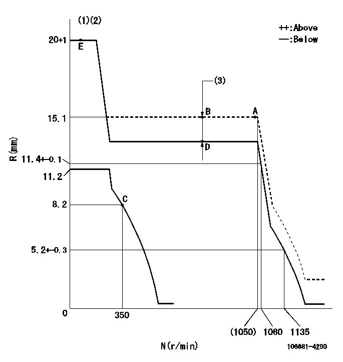
N:Pump speed
R:Rack position (mm)
(1)Target notch: K
(2)Tolerance for racks not indicated: +-0.05mm.
(3)Boost compensator stroke: BCL
----------
K=15 BCL=3.2+-0.1mm
----------
----------
K=15 BCL=3.2+-0.1mm
----------
Speed control lever angle
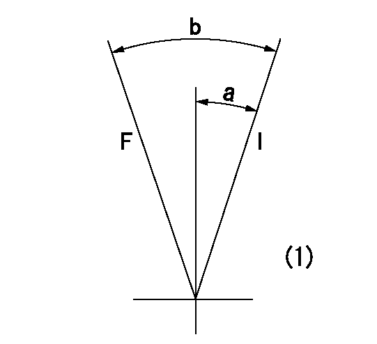
F:Full speed
I:Idle
(1)At the center of the lever key groove
----------
----------
a=16deg+-5deg b=31deg+-5deg
----------
----------
a=16deg+-5deg b=31deg+-5deg
Stop lever angle
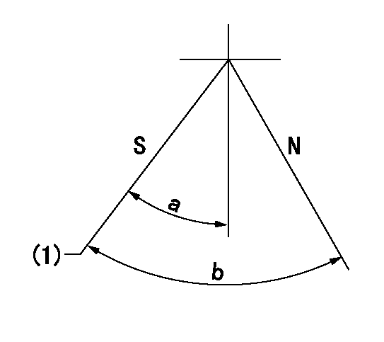
N:Pump normal
S:Stop the pump.
(1)Pump speed aa, rack position bb
----------
aa=0r/min bb=1-0.5mm
----------
a=33deg+-5deg b=(73deg)
----------
aa=0r/min bb=1-0.5mm
----------
a=33deg+-5deg b=(73deg)
Timing setting

(1)Pump vertical direction
(2)Coupling's key groove position at No 1 cylinder's beginning of injection
(3)-
(4)-
----------
----------
a=(20deg)
----------
----------
a=(20deg)
Information:
1. Remove six bolts (1) and remove the fan.2. Loosen the fan belts and alternator belts. Remove the belts. 3. Remove four bolts (3) and adjusting bolt (2). Remove the fan drive.Install Fan Drive
1. Put the fan drive in position on the engine and install the four bolts.2. Install the adjusting bolt. Install the fan and alternator belts. Make an adjustment to the tension. The correct belt tension is 7/8 in. (22 mm) movement for used belts and 3/4in. (19 mm) movement for new belts when measured with the application of a 25 lb. (11 kg) force half way between the two pulleys.3. Tighten the four fan drive bolts.4. Install the fan with the six bolts.Disassemble Fan Drive
start by: a) remove fan drive 1. Remove two bolts and washers (2). Remove hub (1). 2. Bend down the lock plate and remove bolts (4). Remove the lock plate and washer (3). 3. Use tool (A) to remove the pulley from the bracket assembly. 4. Remove the two bearings and the seal with tool (B).5. Remove the spacer.Assemble Fan Drive
1. Put multipurpose grease on the seal. Install the seal on the pulley with tool (A).2. Install the pulley in the bracket assembly. Fill half the space between the two bearings with multipurpose grease.3. Heat two bearings in oil. The temperature of the oil must be 300° 25°F (149° 14°C).
The bearing heating oil used to heat the bearings must have a flash point above 400°F (204°C).
4. Put multipurpose grease on the bearings. Install the bearing, spacer and bearing with tool (A). 5. Install the washer, lock plate and two bolts. Bend the lock plate up.6. Install the hub with the two bolts and lockwashers.end by: a) install fan drive
Have questions with 106681-4290?
Group cross 106681-4290 ZEXEL
Mitsubishi-Heav
Mitsubishi-Heav
Mitsubishi-Heav
Mitsubishi-Heav
Mitsubishi-Heav
Mitsubishi-Heav
Mitsubishi-Heav
Mitsubishi-Heav
Niigata-Urawa
Niigata-Tekkou
Mitsubishi-Heav
106681-4290
INJECTION-PUMP ASSEMBLY