Information injection-pump assembly
ZEXEL
106681-4252
1066814252
Rating:
Service parts 106681-4252 INJECTION-PUMP ASSEMBLY:
1.
_
8.
_
9.
_
11.
Nozzle and Holder
35A61-00060
12.
Open Pre:MPa(Kqf/cm2)
29.4{300}
15.
NOZZLE SET
Include in #1:
106681-4252
as INJECTION-PUMP ASSEMBLY
Cross reference number
ZEXEL
106681-4252
1066814252
Zexel num
Bosch num
Firm num
Name
106681-4252
INJECTION-PUMP ASSEMBLY
Calibration Data:
Adjustment conditions
Test oil
1404 Test oil ISO4113 or {SAEJ967d}
1404 Test oil ISO4113 or {SAEJ967d}
Test oil temperature
degC
40
40
45
Nozzle and nozzle holder
105780-8130
Bosch type code
EFEP215A
Nozzle
105780-0050
Bosch type code
DN6TD119NP1T
Nozzle holder
105780-2090
Bosch type code
EFEP215
Opening pressure
MPa
17.2
Opening pressure
kgf/cm2
175
Injection pipe
Outer diameter - inner diameter - length (mm) mm 8-4-1000
Outer diameter - inner diameter - length (mm) mm 8-4-1000
Overflow valve
131424-3720
Overflow valve opening pressure
kPa
255
221
289
Overflow valve opening pressure
kgf/cm2
2.6
2.25
2.95
Tester oil delivery pressure
kPa
157
157
157
Tester oil delivery pressure
kgf/cm2
1.6
1.6
1.6
Direction of rotation (viewed from drive side)
Left L
Left L
Injection timing adjustment
Direction of rotation (viewed from drive side)
Left L
Left L
Injection order
1-5-3-6-
2-4
Pre-stroke
mm
2.8
2.75
2.85
Beginning of injection position
Governor side NO.1
Governor side NO.1
Difference between angles 1
Cal 1-5 deg. 60 59.5 60.5
Cal 1-5 deg. 60 59.5 60.5
Difference between angles 2
Cal 1-3 deg. 120 119.5 120.5
Cal 1-3 deg. 120 119.5 120.5
Difference between angles 3
Cal 1-6 deg. 180 179.5 180.5
Cal 1-6 deg. 180 179.5 180.5
Difference between angles 4
Cyl.1-2 deg. 240 239.5 240.5
Cyl.1-2 deg. 240 239.5 240.5
Difference between angles 5
Cal 1-4 deg. 300 299.5 300.5
Cal 1-4 deg. 300 299.5 300.5
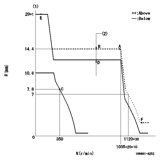
Injection quantity adjustment
Adjusting point
A
Rack position
14.4
Pump speed
r/min
1035
1035
1035
Average injection quantity
mm3/st.
499
490
508
Max. variation between cylinders
%
0
-3
3
Basic
*
Fixing the lever
*
Boost pressure
kPa
93.3
93.3
Boost pressure
mmHg
700
700
Injection quantity adjustment_02
Adjusting point
C
Rack position
7.8+-0.5
Pump speed
r/min
350
350
350
Average injection quantity
mm3/st.
35
32
38
Max. variation between cylinders
%
0
-10
10
Fixing the rack
*
Boost pressure
kPa
0
0
0
Boost pressure
mmHg
0
0
0
Boost compensator adjustment
Pump speed
r/min
750
750
750
Rack position
R1-3.2
Boost pressure
kPa
33.3
30.6
36
Boost pressure
mmHg
250
230
270
Boost compensator adjustment_02
Pump speed
r/min
750
750
750
Rack position
R1(14.4)
Boost pressure
kPa
80
73.3
86.7
Boost pressure
mmHg
600
550
650
Timer adjustment
Pump speed
r/min
450--
Advance angle
deg.
0
0
0
Remarks
Start
Start
Timer adjustment_02
Pump speed
r/min
400
Advance angle
deg.
0.5
Timer adjustment_03
Pump speed
r/min
700
Advance angle
deg.
4
3.5
4.5
Remarks
Finish
Finish
Test data Ex:
Governor adjustment
N:Pump speed
R:Rack position (mm)
(1)Target notch: K
(2)Boost compensator stroke: BCL
----------
K=14 BCL=3.2+-0.1mm
----------
----------
K=14 BCL=3.2+-0.1mm
----------
Speed control lever angle
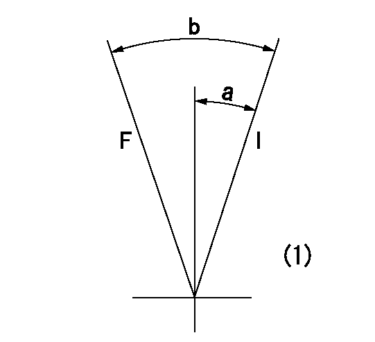
F:Full speed
I:Idle
(1)At the center of the lever key groove
----------
----------
a=18deg+-5deg b=31deg+-5deg
----------
----------
a=18deg+-5deg b=31deg+-5deg
Stop lever angle
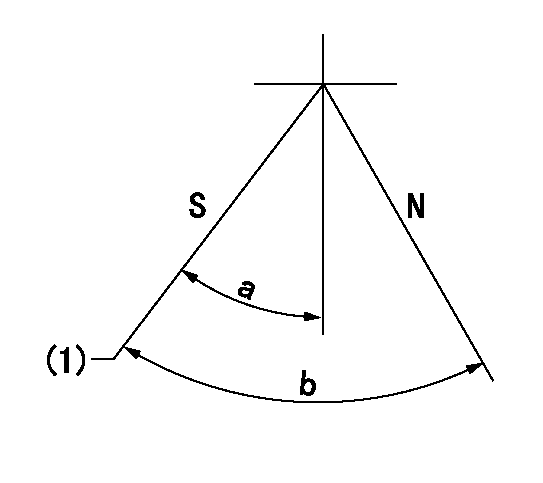
N:Pump normal
S:Stop the pump.
(1)Pump speed aa, rack position bb
----------
aa=0r/min bb=1-0.5mm
----------
a=33deg+-5deg b=(73deg)
----------
aa=0r/min bb=1-0.5mm
----------
a=33deg+-5deg b=(73deg)
Timing setting

(1)Pump vertical direction
(2)Coupling's key groove position at No 1 cylinder's beginning of injection
(3)-
(4)-
----------
----------
a=(20deg)
----------
----------
a=(20deg)
Information:
The problems in this chart are problems that do come about and are normally called "low power." These problems are not necessarily more common than engine problems, but they are possible problems which you need to read and check before an engine is disassembled.Read all of the items but make sure the first four are checked completely before making any engine test. Recommended Procedure1. Tachometer Error ... To check, connect a tachometer of known accuracy to the engine. Run the engine and make a comparison of the readings of the vehicle and test tachometers. If vehicle tachometer is bad, make repairs as necessary or install a new tachometer.2. Engine Operate at High Altitude ... Less oxygen at higher altitudes causes the engine horsepower to go down. There is no effect on the horsepower of the engine for the first 7500 ft. (2280 m) above sea level of operation.3. Brakes Do Not Completely Release ... Check the brakes by feeling all the brake drums. If the brakes of a wheel do not completely release, the brake drum for that wheel will be hotter than the brake drums for the other wheels. With the truck lifted with a jack, the wheels must have free rotation when turned by hand.4. Vehicle Operated in Too High a Gear ... If the operator does not shift the truck correctly, or operates the truck in a "lug" condition (using the truck in too high a gear for engine rpm to go up as accelerator pedal is pushed farther down, or using the truck in a gear where engine rpm goes down with accelerator pedal at maximum travel), poor vehicle performance is the result.5. Extra Engine Driven Equipment ... Air compressors, hydraulic pumps, alternator, and other engine driven equipment that has damage, or that was not installed correctly, or that is not in correct adjustment, can take more horsepower to drive than expected. If necessary, disconnect the equipment and test the engine.6. Speedometer Error ... A bad speedometer does not give the correct speed or the correct indication of fuel consumption. An indication of low speed can cause the operator to feel that he has a power problem.7. Speeds Too High ... The need for more horsepower is easy to see as the speed of the vehicle is increased. This is especially true if the front of the vehicle has a large surface area. Application personnel can give you the horsepower necessary for different vehicle designs at different speeds.8. Overload on Vehicle ... Application personnel can give you the horsepower needs for different vehicles.9. High Moving Resistance ... Soft ground conditions cause a need for more horsepower. To see if the problem is the engine, test the vehicle on a surface known to be good, or test on a chassis dynamometer.10. High Wind Resistance ... The horsepower needs for a truck can be divided into two parts. Part of the horsepower is used to move the vehicle and part is used to get through
Have questions with 106681-4252?
Group cross 106681-4252 ZEXEL
Mitsubishi-Heav
106681-4252
INJECTION-PUMP ASSEMBLY