Information injection-pump assembly
ZEXEL
106681-4250
1066814250
MITSUBISHI-HEAV
35A6500150
35a6500150
Rating:
Service parts 106681-4250 INJECTION-PUMP ASSEMBLY:
1.
_
7.
COUPLING PLATE
8.
_
9.
_
11.
Nozzle and Holder
35A61-00060
12.
Open Pre:MPa(Kqf/cm2)
29.4{300}
15.
NOZZLE SET
Include in #1:
106681-4250
as INJECTION-PUMP ASSEMBLY
Cross reference number
ZEXEL
106681-4250
1066814250
MITSUBISHI-HEAV
35A6500150
35a6500150
Zexel num
Bosch num
Firm num
Name
Calibration Data:
Adjustment conditions
Test oil
1404 Test oil ISO4113 or {SAEJ967d}
1404 Test oil ISO4113 or {SAEJ967d}
Test oil temperature
degC
40
40
45
Nozzle and nozzle holder
105780-8130
Bosch type code
EFEP215A
Nozzle
105780-0050
Bosch type code
DN6TD119NP1T
Nozzle holder
105780-2090
Bosch type code
EFEP215
Opening pressure
MPa
17.2
Opening pressure
kgf/cm2
175
Injection pipe
Outer diameter - inner diameter - length (mm) mm 8-4-1000
Outer diameter - inner diameter - length (mm) mm 8-4-1000
Overflow valve
131424-3720
Overflow valve opening pressure
kPa
255
221
289
Overflow valve opening pressure
kgf/cm2
2.6
2.25
2.95
Tester oil delivery pressure
kPa
157
157
157
Tester oil delivery pressure
kgf/cm2
1.6
1.6
1.6
Direction of rotation (viewed from drive side)
Left L
Left L
Injection timing adjustment
Direction of rotation (viewed from drive side)
Left L
Left L
Injection order
1-5-3-6-
2-4
Pre-stroke
mm
2.8
2.75
2.85
Beginning of injection position
Governor side NO.1
Governor side NO.1
Difference between angles 1
Cal 1-5 deg. 60 59.5 60.5
Cal 1-5 deg. 60 59.5 60.5
Difference between angles 2
Cal 1-3 deg. 120 119.5 120.5
Cal 1-3 deg. 120 119.5 120.5
Difference between angles 3
Cal 1-6 deg. 180 179.5 180.5
Cal 1-6 deg. 180 179.5 180.5
Difference between angles 4
Cyl.1-2 deg. 240 239.5 240.5
Cyl.1-2 deg. 240 239.5 240.5
Difference between angles 5
Cal 1-4 deg. 300 299.5 300.5
Cal 1-4 deg. 300 299.5 300.5
Injection quantity adjustment
Adjusting point
A
Rack position
14.4
Pump speed
r/min
1035
1035
1035
Average injection quantity
mm3/st.
499
490
508
Max. variation between cylinders
%
0
-3
3
Basic
*
Fixing the lever
*
Boost pressure
kPa
137
137
Boost pressure
mmHg
1030
1030
Injection quantity adjustment_02
Adjusting point
C
Rack position
7.8+-0.5
Pump speed
r/min
350
350
350
Average injection quantity
mm3/st.
35
32
38
Max. variation between cylinders
%
0
-10
10
Fixing the rack
*
Boost pressure
kPa
0
0
0
Boost pressure
mmHg
0
0
0
Boost compensator adjustment
Pump speed
r/min
750
750
750
Rack position
R1-3.2
Boost pressure
kPa
62.7
60
65.4
Boost pressure
mmHg
470
450
490
Boost compensator adjustment_02
Pump speed
r/min
750
750
750
Rack position
R1(14.4)
Boost pressure
kPa
124
117.3
130.7
Boost pressure
mmHg
930
880
980
Timer adjustment
Pump speed
r/min
450--
Advance angle
deg.
0
0
0
Remarks
Start
Start
Timer adjustment_02
Pump speed
r/min
400
Advance angle
deg.
0.5
Timer adjustment_03
Pump speed
r/min
700
Advance angle
deg.
4
3.5
4.5
Remarks
Finish
Finish
Test data Ex:
Governor adjustment

N:Pump speed
R:Rack position (mm)
(1)Target notch: K
(2)Boost compensator stroke: BCL
----------
K=14 BCL=3.2+-0.1mm
----------
----------
K=14 BCL=3.2+-0.1mm
----------
Speed control lever angle
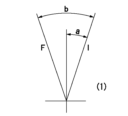
F:Full speed
I:Idle
(1)At the center of the lever key groove
----------
----------
a=18deg+-5deg b=31deg+-5deg
----------
----------
a=18deg+-5deg b=31deg+-5deg
Stop lever angle
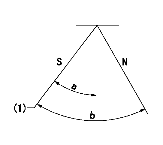
N:Pump normal
S:Stop the pump.
(1)Pump speed aa, rack position bb
----------
aa=0r/min bb=1-0.5mm
----------
a=33deg+-5deg b=(73deg)
----------
aa=0r/min bb=1-0.5mm
----------
a=33deg+-5deg b=(73deg)
Timing setting

(1)Pump vertical direction
(2)Coupling's key groove position at No 1 cylinder's beginning of injection
(3)-
(4)-
----------
----------
a=(20deg)
----------
----------
a=(20deg)
Information:
1. Fuel consumption records must be available before the high fuel consumption complaint can be verified. If symptoms indicate low power, then the low power test should be conducted first, because it could be the cause of the fuel consumption problem. This Primary Engine Test for High Fuel Consumption is the same as the Primary Engine Test for Low Power.2. Visually inspect the fuel system from the fuel tank to the fuel injection lines to see if there are any indications of fuel leaks. Tighten any loose connections found and, if necessary, replace lines that can not be repaired.3. Check the crankcase oil level and the coolant level of the radiator. Remove the boost air line from the AFRC (air-fuel ratio control) during the Primary Engine Test. This will prevent the AFRC from becoming pnuematically activated during the checks. If activated, the AFRC could give an indication of a problem when there is none.4. A slightly lower rpm (15 rpm below low limit) should be expected for the engine in vehicle than the rpm shown in the RACK SETTING INFORMATION. This is caused by the parasitic loads of the engine accessories involved.5. With the engine running, the throttle must have enough travel for the governor control lever to break over (go past the normal governor stop for high idle position) a small amount when the throttle pedal is fully depressed. If full travel is not available, disconnect throttle linkage from governor lever. With throttle linkage disconnected, full travel of governor lever will indicate linkage problems, and the linkage will have to be adjusted. Limited travel of the governor lever will indicate a problem within the governor.6. Only a mechanic with the correct training should change the high idle setting. The procedure is given in this Service Manual under the subject GOVERNOR ADJUSTMENTS.7. If high idle rpm can not be made correct with the high idle adjustment screw, there is a problem inside the governor. Disassemble the governor and check for damaged parts or wrong parts installed in the governor. Some common problems are worn bushings, worn spring seat, or a broken or wrong governor spring.8. Before 8S4627 Circuit Tester is installed, be sure to test the light for correct operation. Test light must come on when the clip of the wire is placed against the probe of the light (replace batteries or bulb if light does not come on). If light comes on and stays on when attached to governor, the insulation is bad or installed wrong in torque spring group or brass terminal. This must be corrected before test is performed.9. With the continuity light installed, quickly push accelerator pedal all the way to the floor. If the fuel control shaft and governor function properly, the continuity light will come on during this free acceleration until high idle is maintained. If the light comes on, this is an indication that the mechanical movement of the governor and fuel injection pump parts operate properly. The vehicle will