Information injection-pump assembly
ZEXEL
106681-4072
1066814072

Rating:
Service parts 106681-4072 INJECTION-PUMP ASSEMBLY:
1.
_
7.
COUPLING PLATE
8.
_
9.
_
11.
Nozzle and Holder
12.
Open Pre:MPa(Kqf/cm2)
21.6{220}
15.
NOZZLE SET
Include in #1:
106681-4072
as INJECTION-PUMP ASSEMBLY
Cross reference number
ZEXEL
106681-4072
1066814072
Zexel num
Bosch num
Firm num
Name
106681-4072
INJECTION-PUMP ASSEMBLY
14CA PE6P,6PD PE
14CA PE6P,6PD PE
Calibration Data:
Adjustment conditions
Test oil
1404 Test oil ISO4113 or {SAEJ967d}
1404 Test oil ISO4113 or {SAEJ967d}
Test oil temperature
degC
40
40
45
Nozzle and nozzle holder
105780-8130
Bosch type code
EFEP215A
Nozzle
105780-0050
Bosch type code
DN6TD119NP1T
Nozzle holder
105780-2090
Bosch type code
EFEP215
Opening pressure
MPa
17.2
Opening pressure
kgf/cm2
175
Injection pipe
Outer diameter - inner diameter - length (mm) mm 8-4-1000
Outer diameter - inner diameter - length (mm) mm 8-4-1000
Overflow valve
131424-7120
Overflow valve opening pressure
kPa
255
221
289
Overflow valve opening pressure
kgf/cm2
2.6
2.25
2.95
Tester oil delivery pressure
kPa
157
157
157
Tester oil delivery pressure
kgf/cm2
1.6
1.6
1.6
Direction of rotation (viewed from drive side)
Right R
Right R
Injection timing adjustment
Direction of rotation (viewed from drive side)
Right R
Right R
Injection order
1-4-2-6-
3-5
Pre-stroke
mm
4.1
4.05
4.15
Beginning of injection position
Drive side NO.1
Drive side NO.1
Difference between angles 1
Cal 1-4 deg. 60 59.5 60.5
Cal 1-4 deg. 60 59.5 60.5
Difference between angles 2
Cyl.1-2 deg. 120 119.5 120.5
Cyl.1-2 deg. 120 119.5 120.5
Difference between angles 3
Cal 1-6 deg. 180 179.5 180.5
Cal 1-6 deg. 180 179.5 180.5
Difference between angles 4
Cal 1-3 deg. 240 239.5 240.5
Cal 1-3 deg. 240 239.5 240.5
Difference between angles 5
Cal 1-5 deg. 300 299.5 300.5
Cal 1-5 deg. 300 299.5 300.5
Injection quantity adjustment
Adjusting point
A
Rack position
13
Pump speed
r/min
1150
1150
1150
Each cylinder's injection qty
mm3/st.
351
340.5
361.5
Basic
*
Fixing the lever
*
Boost pressure
kPa
46.7
46.7
Boost pressure
mmHg
350
350
Injection quantity adjustment_02
Adjusting point
B
Rack position
6.7+-0.5
Pump speed
r/min
225
225
225
Each cylinder's injection qty
mm3/st.
20.6
18.5
22.7
Fixing the rack
*
Boost pressure
kPa
0
0
0
Boost pressure
mmHg
0
0
0
Injection quantity adjustment_03
Adjusting point
C
Rack position
-
Pump speed
r/min
100
100
100
Average injection quantity
mm3/st.
295
295
325
Fixing the lever
*
Boost pressure
kPa
0
0
0
Boost pressure
mmHg
0
0
0
Rack limit
*
Boost compensator adjustment
Pump speed
r/min
500
500
500
Rack position
R1-2.5
Boost pressure
kPa
6.7
4
9.4
Boost pressure
mmHg
50
30
70
Boost compensator adjustment_02
Pump speed
r/min
500
500
500
Rack position
R1(13)
Boost pressure
kPa
33.3
33.3
33.3
Boost pressure
mmHg
250
250
250
Timer adjustment
Pump speed
r/min
1150++
Advance angle
deg.
0
0
0
Remarks
Do not advance until starting N = 1150.
Do not advance until starting N = 1150.
Timer adjustment_02
Pump speed
r/min
-
Advance angle
deg.
2
2
2
Remarks
Measure the actual speed, stop
Measure the actual speed, stop
Test data Ex:
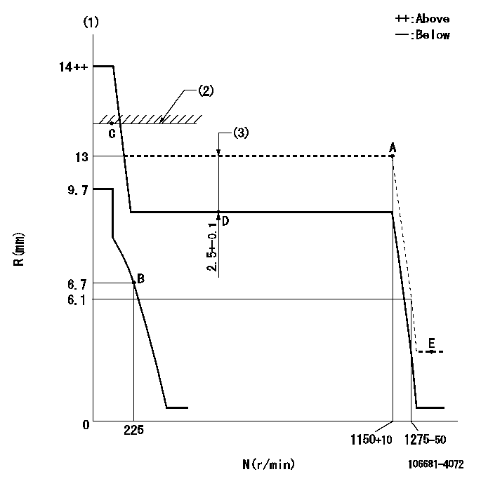
Governor adjustment

N:Pump speed
R:Rack position (mm)
(1)Target notch: K
(2)RACK LIMIT
(3)Boost compensator stroke
----------
K=7
----------
----------
K=7
----------
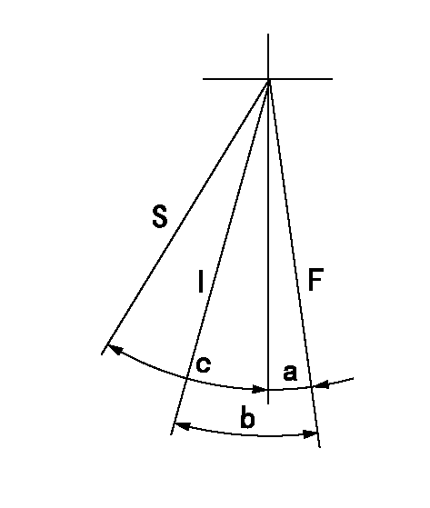
Speed control lever angle

F:Full speed
I:Idle
S:Stop
----------
----------
a=9deg+-5deg b=34deg+-5deg c=35deg+-3deg
----------
----------
a=9deg+-5deg b=34deg+-5deg c=35deg+-3deg
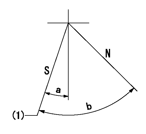
Stop lever angle

N:Pump normal
S:Stop the pump.
(1)Speed = aa, rack position = bb (sealed at shipping)
----------
aa=0r/min bb=1-0.2mm
----------
a=25deg+-5deg b=70deg+-5deg
----------
aa=0r/min bb=1-0.2mm
----------
a=25deg+-5deg b=70deg+-5deg
Timing setting

(1)Pump vertical direction
(2)Coupling's key groove position at No 1 cylinder's beginning of injection
(3)-
(4)-
----------
----------
a=(60deg)
----------
----------
a=(60deg)
Information:
01Nov2005
U-511
A-508
D-508
O-507
TM-503
Parts stock action only
PRODUCT IMPROVEMENT PROGRAM FOR REMOVING REMAN 3600 INJECTORS FROM DEALERS PARTS STOCK
1290 PI70200
The information supplied in this service letter may not be valid after the termination date of this program.Do not perform the work outlined in this Service Letter after the termination date without first contacting your Caterpillar product analyst.
TERMINATION DATE
01Feb2006
PROBLEM
Some remanufactured 3600 unit injectors may have been built with a case that does not have an o-ring groove. The 061-9455 o-ring prevents build up of carbon on the injector body. Excessive carbon build up can make the injector difficult to remove.
PARTS NEEDED
No parts needed for this program
ACTION REQUIRED
See the attached Rework Procedure.
SERVICE CLAIM ALLOWANCE
Submit one claim for all 10R-1252, 10R-1253 and 10R-1254 injectors with the old case design that were removed from dealer stock.
PARTS DISPOSITION
Return all Reman Injectors with the old case design that were removed from parts stock and a copy of the claim to:
Caterpillar Service Claims Room
Pioneer Park Building C, Dock 22
8201 N. University Street
Peoria, IL 61615
Attn: Scott Weber / Alex Miller
Rework Procedure
Inspect all 10R-1252, 10R-1253 and 10R-1254 injectors with a date code less than 06220501. Any injectors that are missing the o-ring groove must be removed from parts stock. Image 1 shows the case with the o-ring groove and Image 2 shows the case without the o-ring groove.
Image1.1.1
Image1.1.2
Have questions with 106681-4072?
Group cross 106681-4072 ZEXEL
Daihatsu
Komatsu
Komatsu
Niigata-Urawa
Niigata-Urawa
Niigata-Tekkou
Mitsubishi-Heav
Shinko-Engin.
Yanmar
106681-4072
INJECTION-PUMP ASSEMBLY