Information injection-pump assembly
ZEXEL
106681-4030
1066814030
NIIGATA-URAWA
74W47001A
74w47001a

Rating:
Cross reference number
ZEXEL
106681-4030
1066814030
NIIGATA-URAWA
74W47001A
74w47001a
Zexel num
Bosch num
Firm num
Name
Calibration Data:
Adjustment conditions
Test oil
1404 Test oil ISO4113 or {SAEJ967d}
1404 Test oil ISO4113 or {SAEJ967d}
Test oil temperature
degC
40
40
45
Nozzle and nozzle holder
105780-8130
Bosch type code
EFEP215A
Nozzle
105780-0050
Bosch type code
DN6TD119NP1T
Nozzle holder
105780-2090
Bosch type code
EFEP215
Opening pressure
MPa
17.2
Opening pressure
kgf/cm2
175
Injection pipe
Outer diameter - inner diameter - length (mm) mm 8-3-600
Outer diameter - inner diameter - length (mm) mm 8-3-600
Overflow valve
131424-7120
Overflow valve opening pressure
kPa
255
221
289
Overflow valve opening pressure
kgf/cm2
2.6
2.25
2.95
Tester oil delivery pressure
kPa
157
157
157
Tester oil delivery pressure
kgf/cm2
1.6
1.6
1.6
Direction of rotation (viewed from drive side)
Left L
Left L
Injection timing adjustment
Direction of rotation (viewed from drive side)
Left L
Left L
Injection order
1-4-2-6-
3-5
Pre-stroke
mm
3.5
3.45
3.55
Beginning of injection position
Drive side NO.1
Drive side NO.1
Difference between angles 1
Cal 1-4 deg. 60 59.5 60.5
Cal 1-4 deg. 60 59.5 60.5
Difference between angles 2
Cyl.1-2 deg. 120 119.5 120.5
Cyl.1-2 deg. 120 119.5 120.5
Difference between angles 3
Cal 1-6 deg. 180 179.5 180.5
Cal 1-6 deg. 180 179.5 180.5
Difference between angles 4
Cal 1-3 deg. 240 239.5 240.5
Cal 1-3 deg. 240 239.5 240.5
Difference between angles 5
Cal 1-5 deg. 300 299.5 300.5
Cal 1-5 deg. 300 299.5 300.5
Injection quantity adjustment
Adjusting point
A
Rack position
12.9
Pump speed
r/min
1100
1100
1100
Average injection quantity
mm3/st.
290
285
295
Max. variation between cylinders
%
0
-3
3
Basic
*
Fixing the lever
*
Injection quantity adjustment_02
Adjusting point
B
Rack position
8.8+-0.5
Pump speed
r/min
250
250
250
Average injection quantity
mm3/st.
30
27
33
Max. variation between cylinders
%
0
-10
10
Fixing the rack
*
Timer adjustment
Pump speed
r/min
400--
Advance angle
deg.
0
0
0
Remarks
Start
Start
Timer adjustment_02
Pump speed
r/min
350
Advance angle
deg.
0.5
Timer adjustment_03
Pump speed
r/min
650
Advance angle
deg.
4
3.5
4.5
Remarks
Finish
Finish
Test data Ex:
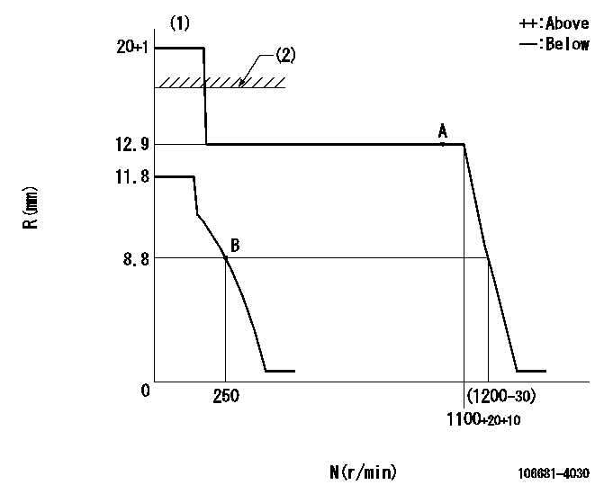
Governor adjustment

N:Pump speed
R:Rack position (mm)
(1)Notch fixed: K
(2)RACK LIMIT: RAL
----------
K=20 RAL=13.9+0.2mm
----------
----------
K=20 RAL=13.9+0.2mm
----------
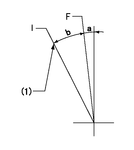
Speed control lever angle

F:Full speed
I:Idle
(1)Stopper bolt setting
----------
----------
a=13deg+-5deg b=(34deg)+-5deg
----------
----------
a=13deg+-5deg b=(34deg)+-5deg
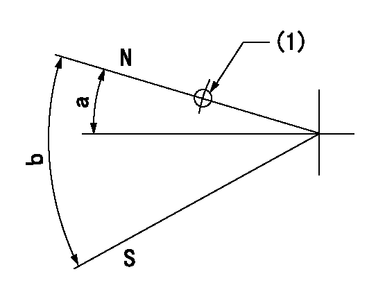
Stop lever angle

N:Pump normal
S:Stop the pump.
(1)Use the hole at R = aa
----------
aa=17mm
----------
a=27deg+-5deg b=53deg+-5deg
----------
aa=17mm
----------
a=27deg+-5deg b=53deg+-5deg
Timing setting

(1)Pump vertical direction
(2)Coupling's key groove position at No 1 cylinder's beginning of injection
(3)-
(4)-
----------
----------
a=(1deg)
----------
----------
a=(1deg)
Information:
Table 1
Required Parts
Item Qty New Part Number Part Name Former Part Number(1)
1 1 573-8722 Coolant Tank As 469-9108
2 1 586-9617 Bracket As 491-3429
3 1 570-0813 Hose 474-9783
(1) The former part number listed is for reference only and may differ.Refer to "Replacement Procedure" for the procedure to install a new coolant tank assembly (1).Replacement Procedure
Illustration 1 g06464028
(A) Hood
Illustration 2 g06464029
(B) Tank assembly
Remove hood (A) to gain access to tank assembly (B).
Illustration 3 g06464030
(B) Tank assembly
(C) Hose
(D) Clamp
Disconnect hose (C) from tank assembly (B) by removing clamp (D).
Illustration 4 g06464533
(E) Special connector
(F) Hose assembly
(H) Clips
Illustration 5 g06464539
(G) Bolts
Disconnect special connector (E). Remove tank assembly with hose assembly (F) by removing bolts (G). Remove clips (H) and special connector (E) from hose assembly (F).
Illustration 6 g06464548
(K) Bracket
(L) Bolts
Remove bracket (K) by removing bolts (L).
Illustration 7 g06464563
(1) 573-8722 Coolant Tank As
(3) 570-0813 Hose
(E) Special connector
(H) Clips
Illustration 8 g06464617
(D1) 27 degrees
(D2) 15 mm (0.6 inch)
(D3) 10 mm (0.4 inch)
Sub-assemble new tank assembly (1), hose (3), and special connector (E) with clips (H).Note: Align hose (3) and special connector (E) at the correct angle. Refer to Illustration 7 and 8 for proper alignment.
Illustration 9 g06464631
(2) 586-9617 Bracket As
(L) Bolts
Install new bracket assembly (2) with bolts (L). Torque bolts (L) to 12 3 N m (106.2 26.6 lb in)
Illustration 10 g06464633
(1) 573-8722 Coolant Tank As
(E) Special connector
(G) Bolts
Install tank assembly (1) with bolts (G) and connect special connector (E). Tighten bolts (G) to 12 3 N m (106.2 26.6 lb in).
Illustration 11 g06464637
(1) 573-8722 Coolant Tank As
(C) Hose
(D) Clamp
Reconnect hose (C) to the tank assembly (1) with clamp (D).
Reinstall hood. Refer to Step 1.