Information injection-pump assembly
ZEXEL
106681-4023
1066814023

Rating:
Service parts 106681-4023 INJECTION-PUMP ASSEMBLY:
1.
_
2.
FUEL INJECTION PUMP
3.
GOVERNOR
7.
COUPLING PLATE
8.
_
9.
_
11.
Nozzle and Holder
6212-11-3202
12.
Open Pre:MPa(Kqf/cm2)
24.5{250}
15.
NOZZLE SET
Include in #1:
106681-4023
as INJECTION-PUMP ASSEMBLY
Cross reference number
ZEXEL
106681-4023
1066814023
Zexel num
Bosch num
Firm num
Name
Calibration Data:
Adjustment conditions
Test oil
1404 Test oil ISO4113 or {SAEJ967d}
1404 Test oil ISO4113 or {SAEJ967d}
Test oil temperature
degC
40
40
45
Nozzle and nozzle holder
105780-8130
Bosch type code
EFEP215A
Nozzle
105780-0050
Bosch type code
DN6TD119NP1T
Nozzle holder
105780-2090
Bosch type code
EFEP215
Opening pressure
MPa
17.2
Opening pressure
kgf/cm2
175
Injection pipe
Outer diameter - inner diameter - length (mm) mm 8-3-600
Outer diameter - inner diameter - length (mm) mm 8-3-600
Overflow valve
131424-7120
Overflow valve opening pressure
kPa
255
221
289
Overflow valve opening pressure
kgf/cm2
2.6
2.25
2.95
Tester oil delivery pressure
kPa
157
157
157
Tester oil delivery pressure
kgf/cm2
1.6
1.6
1.6
Direction of rotation (viewed from drive side)
Right R
Right R
Injection timing adjustment
Direction of rotation (viewed from drive side)
Right R
Right R
Injection order
1-5-3-6-
2-4
Pre-stroke
mm
3.5
3.45
3.55
Beginning of injection position
Drive side NO.1
Drive side NO.1
Difference between angles 1
Cal 1-5 deg. 60 59.5 60.5
Cal 1-5 deg. 60 59.5 60.5
Difference between angles 2
Cal 1-3 deg. 120 119.5 120.5
Cal 1-3 deg. 120 119.5 120.5
Difference between angles 3
Cal 1-6 deg. 180 179.5 180.5
Cal 1-6 deg. 180 179.5 180.5
Difference between angles 4
Cyl.1-2 deg. 240 239.5 240.5
Cyl.1-2 deg. 240 239.5 240.5
Difference between angles 5
Cal 1-4 deg. 300 299.5 300.5
Cal 1-4 deg. 300 299.5 300.5
Injection quantity adjustment
Adjusting point
A
Rack position
15.3
Pump speed
r/min
1050
1050
1050
Average injection quantity
mm3/st.
345.2
343.2
347.2
Max. variation between cylinders
%
0
-3
3
Basic
*
Fixing the lever
*
Boost pressure
kPa
86.6
86.6
Boost pressure
mmHg
650
650
Injection quantity adjustment_02
Adjusting point
B
Rack position
9.3+-0.5
Pump speed
r/min
300
300
300
Average injection quantity
mm3/st.
20
18.5
21.5
Max. variation between cylinders
%
0
-15
15
Fixing the rack
*
Boost pressure
kPa
0
0
0
Boost pressure
mmHg
0
0
0
Remarks
Adjust only variation between cylinders; adjust governor according to governor specifications.
Adjust only variation between cylinders; adjust governor according to governor specifications.
Boost compensator adjustment
Pump speed
r/min
600
600
600
Rack position
13.2
Boost pressure
kPa
12
9.3
14.7
Boost pressure
mmHg
90
70
110
Boost compensator adjustment_02
Pump speed
r/min
600
600
600
Rack position
16
Boost pressure
kPa
58.7
52
65.4
Boost pressure
mmHg
440
390
490
Timer adjustment
Pump speed
r/min
800--
Advance angle
deg.
0
0
0
Remarks
Start
Start
Timer adjustment_02
Pump speed
r/min
750
Advance angle
deg.
0.5
Timer adjustment_03
Pump speed
r/min
1050
Advance angle
deg.
2.5
2
3
Remarks
Finish
Finish
Test data Ex:
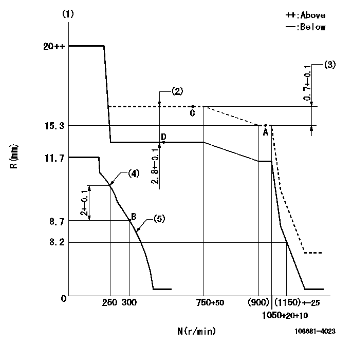
Governor adjustment

N:Pump speed
R:Rack position (mm)
(1)Notch fixed: K
(2)Boost compensator stroke
(3)Rack difference between N = N1 and N = N2
(4)Set the No 1 idle sub spring.
(5)Set the 2nd idle sub spring.
----------
K=20 N1=1050r/min N2=750r/min
----------
----------
K=20 N1=1050r/min N2=750r/min
----------
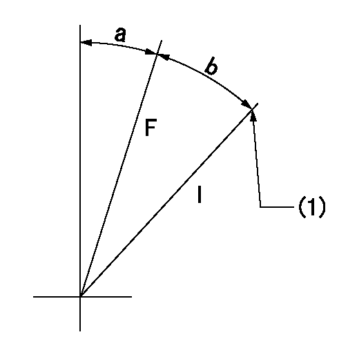
Speed control lever angle

F:Full speed
I:Idle
(1)Stopper bolt setting
----------
----------
a=(32deg)+-5deg b=(26deg)+-5deg
----------
----------
a=(32deg)+-5deg b=(26deg)+-5deg
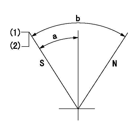
Stop lever angle

N:Pump normal
S:Stop the pump.
(1)Pump speed aa, rack position bb
(2)(Seal at delivery.)
----------
aa=0r/min bb=1-0.2mm
----------
a=29deg+-5deg b=(73deg)
----------
aa=0r/min bb=1-0.2mm
----------
a=29deg+-5deg b=(73deg)
Timing setting

(1)Pump vertical direction
(2)Coupling's key groove position at No 1 cylinder's beginning of injection
(3)-
(4)-
----------
----------
a=(30deg)
----------
----------
a=(30deg)
Information:
This Program can be administered aftera failure occurs. The decision whether to apply the Program is made bythe dealer. When reporting the repair, use "PS50440" as the Part numberand "7755" as the Group Number and use 135579 DTF Code. Use "96" as theWarranty Claim Description Code and use "Z" as the SIMS Description Code. The information supplied in this serviceletter may not be valid after the termination date of this program. Donot perform the work outlined in this Service Letter after the terminationdate without first contacting your Caterpillar product analyst. Dealer and District are responsible fordetermining eligibility. Engine installations that are known to have airentry into fuel supply are not eligible for this program.TERMINATION DATE
April 30, 2003PROBLEM
The fuel injector tip may fail on certain 3500BMarine and Genset enginesAFFECTED PRODUCT
Group1
Model Identification Number
3508B 2HW125-1601TW249-2713DW153-161
3512B 4AW329-4282GW234-277
3512B M/AUX 1PW355-361
3516B 1NW122-1342FW183-2123CW236-242
Group2
Model Identification Number
3508B 2BM139-151
3512B 7HM207-224
3516B 8CN170-180
Group3
Model Identification Number
3512B 4TN207-3118EM317-352
3516B 8KN368-4159AN175-201
Group4
Model Identification Number
3508B 7SM229-328
Group5
Model Identification Number
3508B 3DM157-206 PARTS NEEDED
Group 1* - 0R9944
* 8 for 3508 Engines (2HW125-160, 1TW249-271, 3DW153-161)
12 for 3512 Engines (4AW329-428, 2GW234-277, 1PW355-361)
16 for 3516 Engines (1NW122-134, 2FW183-212, 3CW236-242)Group 2* - 0R8691
* 8 for 3508 Engines (2BM139-151)
12 for 3512 Engines (7HM207-224)
16 for 3516 Engines (8CN170-180)Group 3* - 0R8688
* 12 for 3508 Engines (4TN207-311, 8EM317-352)
16 for 3512 Engines (8KN368-415, 9AN175-201)Group 4* - 0R8688 ?OR- 0R8690
* 8 for 3508 Engines (7SM229-328)Group 5* - 0R8690
* 8 for 3508 Engines (3DM157-206)ACTION REQUIRED
Replace all injectors and resultant damage, perstandard repair procedures (SENR6564-04 for injector R&I).SERVICE CLAIM ALLOWANCES
Product smu/age whichever comes first Caterpillar Dealer Suggested Customer Suggested
Parts Labor Hrs Parts Labor Hrs Parts Labor Hrs
0-5000 hrs(0-24 mos) 100% 100% 0 0 0 0
5001-10000 hrs(24-48 mos) 33.3% 50% 0 0 50% 50%
NOTE : Maximum allowable labor for injectorreplacement is 1 hour plus 0.5 hours per injector. Use labor times listedin the Time Requirement Guide for replacing the resultant damage.PARTS DISPOSITION
***** North American and Canadian Dealers*****Return Complete Injector Sets to:Caterpillar Inc.Attn: Fergal O?Shea
Service Claims Room (PS50440)
8201 N. University
Peoria, IL 61615***** All Other Dealers *****Handle the parts in accordance with your WarrantyBulletin on
warranty parts handling.