Information injection-pump assembly
BOSCH
F 01G 09U 091
f01g09u091
ZEXEL
106681-3001
1066813001
HINO
220206450B
220206450b
Rating:
Service parts 106681-3001 INJECTION-PUMP ASSEMBLY:
1.
_
7.
COUPLING PLATE
8.
_
9.
_
11.
Nozzle and Holder
236003621A
12.
Open Pre:MPa(Kqf/cm2)
16.7(170)/23.5(240)
14.
NOZZLE
Include in #1:
106681-3001
as INJECTION-PUMP ASSEMBLY
Cross reference number
BOSCH
F 01G 09U 091
f01g09u091
ZEXEL
106681-3001
1066813001
HINO
220206450B
220206450b
Zexel num
Bosch num
Firm num
Name
106681-3001
F 01G 09U 091
220206450B HINO
INJECTION-PUMP ASSEMBLY
K13C-TI K 14CA INJECTION PUMP ASSY PE6P,6PD PE
K13C-TI K 14CA INJECTION PUMP ASSY PE6P,6PD PE
Calibration Data:
Adjustment conditions
Test oil
1404 Test oil ISO4113 or {SAEJ967d}
1404 Test oil ISO4113 or {SAEJ967d}
Test oil temperature
degC
40
40
45
Nozzle and nozzle holder
105780-8130
Bosch type code
EFEP215A
Nozzle
105780-0050
Bosch type code
DN6TD119NP1T
Nozzle holder
105780-2090
Bosch type code
EFEP215
Opening pressure
MPa
17.2
Opening pressure
kgf/cm2
175
Injection pipe
Outer diameter - inner diameter - length (mm) mm 8-4-1000
Outer diameter - inner diameter - length (mm) mm 8-4-1000
Overflow valve
131424-9020
Overflow valve opening pressure
kPa
255
221
289
Overflow valve opening pressure
kgf/cm2
2.6
2.25
2.95
Tester oil delivery pressure
kPa
255
255
255
Tester oil delivery pressure
kgf/cm2
2.6
2.6
2.6
Direction of rotation (viewed from drive side)
Left L
Left L
Injection timing adjustment
Direction of rotation (viewed from drive side)
Left L
Left L
Injection order
1-4-2-6-
3-5
Pre-stroke
mm
3.7
3.67
3.73
Beginning of injection position
Drive side NO.1
Drive side NO.1
Difference between angles 1
Cal 1-4 deg. 60 59.75 60.25
Cal 1-4 deg. 60 59.75 60.25
Difference between angles 2
Cyl.1-2 deg. 120 119.75 120.25
Cyl.1-2 deg. 120 119.75 120.25
Difference between angles 3
Cal 1-6 deg. 180 179.75 180.25
Cal 1-6 deg. 180 179.75 180.25
Difference between angles 4
Cal 1-3 deg. 240 239.75 240.25
Cal 1-3 deg. 240 239.75 240.25
Difference between angles 5
Cal 1-5 deg. 300 299.75 300.25
Cal 1-5 deg. 300 299.75 300.25
Injection quantity adjustment
Adjusting point
A
Rack position
14
Pump speed
r/min
1000
1000
1000
Average injection quantity
mm3/st.
337
334
340
Max. variation between cylinders
%
0
-3
3
Basic
*
Fixing the lever
*
Boost pressure
kPa
37.3
37.3
Boost pressure
mmHg
280
280
Injection quantity adjustment_02
Adjusting point
-
Rack position
8.9+-0.5
Pump speed
r/min
360
360
360
Average injection quantity
mm3/st.
14
11
17
Max. variation between cylinders
%
0
-15
15
Fixing the rack
*
Boost pressure
kPa
0
0
0
Boost pressure
mmHg
0
0
0
Remarks
Adjust only variation between cylinders; adjust governor according to governor specifications.
Adjust only variation between cylinders; adjust governor according to governor specifications.
Injection quantity adjustment_03
Adjusting point
D
Rack position
14.3++
Pump speed
r/min
100
100
100
Average injection quantity
mm3/st.
230
225
235
Fixing the lever
*
Boost pressure
kPa
0
0
0
Boost pressure
mmHg
0
0
0
Rack limit
*
Boost compensator adjustment
Pump speed
r/min
900
900
900
Rack position
R1-1.8
Boost pressure
kPa
6.7
4
9.4
Boost pressure
mmHg
50
30
70
Boost compensator adjustment_02
Pump speed
r/min
900
900
900
Rack position
R1(14)
Boost pressure
kPa
24
24
24
Boost pressure
mmHg
180
180
180
Timer adjustment
Pump speed
r/min
800--
Advance angle
deg.
0
0
0
Remarks
Start
Start
Timer adjustment_02
Pump speed
r/min
750
Advance angle
deg.
0.3
Timer adjustment_03
Pump speed
r/min
950
Advance angle
deg.
2.5
2.2
2.8
Remarks
Finish
Finish
Test data Ex:
Governor adjustment
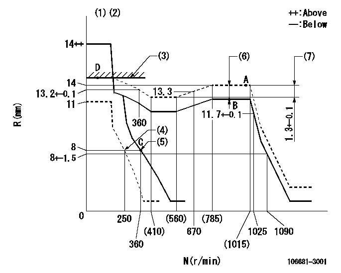
N:Pump speed
R:Rack position (mm)
(1)Notch fixed: K
(2)Tolerance for racks not indicated: +-0.05mm.
(3)RACK LIMIT
(4)Set idle sub-spring
(5)Main spring setting
(6)Boost compensator stroke: BCL
(7)Rack difference between N = N1 and N = N2
----------
K=14 BCL=1.8+-0.1mm N1=1000r/min N2=500r/min
----------
----------
K=14 BCL=1.8+-0.1mm N1=1000r/min N2=500r/min
----------
Speed control lever angle

F:Full speed
I:Idle
(1)Stopper bolt setting
----------
----------
a=(5deg)+-5deg b=(27deg)+-5deg
----------
----------
a=(5deg)+-5deg b=(27deg)+-5deg
Stop lever angle
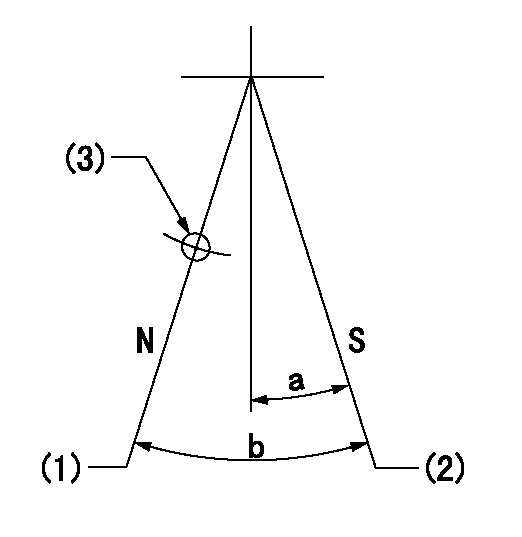
N:Pump normal
S:Stop the pump.
(1)Normal
(2)Pump speed aa and rack position bb (to be sealed at delivery)
(3)Use the hole above R = cc
----------
aa=0r/min bb=1-0.5mm cc=20mm
----------
a=10deg+-5deg b=70deg+-5deg
----------
aa=0r/min bb=1-0.5mm cc=20mm
----------
a=10deg+-5deg b=70deg+-5deg
0000001501 TAMPER PROOF

Tamperproofing-equipped boost compensator cover installation procedure
(A) After adjusting the boost compensator, tighten the bolts to remove the heads.
(1)Before adjusting the governor and the boost compensator, tighten the screw to the specified torque.
(Tightening torque T = T1 maximum)
(2)After adjusting the governor and the boost compensator, tighten to the specified torque to break off the bolt heads.
(Tightening torque T = T2)
----------
T1=2.5N-m(0.25kgf-m) T2=2.9~4.4N-m(0.3~0.45kgf-m)
----------
----------
T1=2.5N-m(0.25kgf-m) T2=2.9~4.4N-m(0.3~0.45kgf-m)
----------
Timing setting

(1)Pump vertical direction
(2)Coupling's key groove position at No 1 cylinder's beginning of injection
(3)B.T.D.C.: aa
(4)-
----------
aa=14deg
----------
a=(2deg)
----------
aa=14deg
----------
a=(2deg)
Information:
The information supplied in this service letter may not be valid after the termination date of this program. Do not perform the work outlined in this Service Letter after the termination date without first contacting your Caterpillar product analyst.
This Program can be administered either before or after a failure. In either case the decision whether to apply the Program is made by the dealer. When reporting the repair, use "PS4338" as the Part Number and "7755" as the Group Number. If administered before failure, use "56" as the Warranty Claim Description Code and use "T" as the SIMS Description Code. If administered after failure, use "96" as the Warranty Claim Description Code and use "Z" as the SIMS Description Code.
Termination Date
June 30, 1999Problem
The 7E7202 Button used in the 7E7205 Rocker Arm Assembly may become separated from the rocker arm when a unit injector sticks during engine operation. Damage to the unit injector may result when the engine is operated with the button separated from the rocker arm.
Affected Product
Model & Identification Number
3606 (8RB298, 8RB585, 8RB590, 8RB591)
3608 (6MC246, 6MC255, 6MC310, 6MC311, 6MC313, 6MC332, 6MC333, 6MC380, 6MC410, 6MC411, 6MC415 , 6MC481, 6MC482, 6MC488-490)
3612 (9RC121, 9RC130, 9RC131, 9RC143, 9RC187, 9RC188)
3616 (1PD24, 1PD82-85, 1PD103, 1PD104, 1PD108-110, 1PD112-115, 1PD117, 1PD119-143 , 1PD148, 1PD154, 1PD156-161, 1PD163, 1PD165, 1PD167, 1PD168, 1PD206 , 1PD211-215, 1PD217, 1PD238, 1PD241-244, 1PD251-261, 1PD264, 1PD267-275 )
Parts Needed
1 - 1514881 Button1 - 5P6031 Wire-LockAction Required
See the attached rework procedure.
Service Claim Allowances
Parts Disposition
Handle the parts in accordance with your Warranty Bulletin on warranty parts handling.
Attach.(1-Rework Procedure)Rework Procedure
The following procedure provides instructions to install the 1514881 Button onto the 1514918 Rocker Insert used in the 7E7205 Rocker Arm Assembly for the 3600 Series Engine. The button requires a 5P6031 Lock Wire to secure it to the insert.
Recommended Tooling
- Standard or inch tip screwdriver- 10 or 12 inch multiple position pliers (Channel Locks)- 12 oz Ball Peen Hammer- (2.4 mm) PunchInstallation Of 1514881 Button
1. Remove the 1267473 Rocker Arm Group from the engine and place on a work bench. Use a standard or inch tip screw driver to remove the previous 7E7202 Button and 5P8119 O-Ring by prying between the button and rocker arm. 2. Be sure no damage has occurred to the oil passage in the insert. If damage has occurred it is necessary to replace the insert. A 1514883 Rocker Arm Assembly should be used which includes the 1514881 Button and 1514882 Locking Wire assembled to the insert. 3. If there is no damage to the insert hold the 1514881 Button on the insert using a pair of 10 or 12 inch multiple position pliers. The button has a 2.6 mm (0.10 inch) hole in the side. Make sure the hole in the side of the button is in a position so the wire can be inserted. Insert the wire into the hole. 4. With one person holding the button squarely on the insert with pliers, another person is to hold the wire firmly. Apply pressure on the wire and use
Have questions with 106681-3001?
Group cross 106681-3001 ZEXEL
Hino
106681-3001
F 01G 09U 091
220206450B
INJECTION-PUMP ASSEMBLY
K13C-TI
K13C-TI