Information injection-pump assembly
BOSCH
9 400 613 443
9400613443
ZEXEL
106681-3000
1066813000
HINO
220206450A
220206450a
Rating:
Service parts 106681-3000 INJECTION-PUMP ASSEMBLY:
1.
_
7.
COUPLING PLATE
8.
_
9.
_
11.
Nozzle and Holder
236003620A
12.
Open Pre:MPa(Kqf/cm2)
16.7{170}/23.5{240}
14.
NOZZLE
Include in #1:
106681-3000
as INJECTION-PUMP ASSEMBLY
Cross reference number
BOSCH
9 400 613 443
9400613443
ZEXEL
106681-3000
1066813000
HINO
220206450A
220206450a
Zexel num
Bosch num
Firm num
Name
9 400 613 443
220206450A HINO
INJECTION-PUMP ASSEMBLY
K13C-TI * K 14CA INJECTION PUMP ASSY PE6P,6PD PE
K13C-TI * K 14CA INJECTION PUMP ASSY PE6P,6PD PE
Calibration Data:
Adjustment conditions
Test oil
1404 Test oil ISO4113 or {SAEJ967d}
1404 Test oil ISO4113 or {SAEJ967d}
Test oil temperature
degC
40
40
45
Nozzle and nozzle holder
105780-8130
Bosch type code
EFEP215A
Nozzle
105780-0050
Bosch type code
DN6TD119NP1T
Nozzle holder
105780-2090
Bosch type code
EFEP215
Opening pressure
MPa
17.2
Opening pressure
kgf/cm2
175
Injection pipe
Outer diameter - inner diameter - length (mm) mm 8-4-1000
Outer diameter - inner diameter - length (mm) mm 8-4-1000
Overflow valve
131424-9020
Overflow valve opening pressure
kPa
255
221
289
Overflow valve opening pressure
kgf/cm2
2.6
2.25
2.95
Tester oil delivery pressure
kPa
255
255
255
Tester oil delivery pressure
kgf/cm2
2.6
2.6
2.6
Direction of rotation (viewed from drive side)
Left L
Left L
Injection timing adjustment
Direction of rotation (viewed from drive side)
Left L
Left L
Injection order
1-4-2-6-
3-5
Pre-stroke
mm
3.7
3.67
3.73
Beginning of injection position
Drive side NO.1
Drive side NO.1
Difference between angles 1
Cal 1-4 deg. 60 59.75 60.25
Cal 1-4 deg. 60 59.75 60.25
Difference between angles 2
Cyl.1-2 deg. 120 119.75 120.25
Cyl.1-2 deg. 120 119.75 120.25
Difference between angles 3
Cal 1-6 deg. 180 179.75 180.25
Cal 1-6 deg. 180 179.75 180.25
Difference between angles 4
Cal 1-3 deg. 240 239.75 240.25
Cal 1-3 deg. 240 239.75 240.25
Difference between angles 5
Cal 1-5 deg. 300 299.75 300.25
Cal 1-5 deg. 300 299.75 300.25
Injection quantity adjustment
Adjusting point
A
Rack position
14
Pump speed
r/min
1000
1000
1000
Average injection quantity
mm3/st.
337
334
340
Max. variation between cylinders
%
0
-3
3
Basic
*
Fixing the lever
*
Boost pressure
kPa
37.3
37.3
Boost pressure
mmHg
280
280
Injection quantity adjustment_02
Adjusting point
-
Rack position
8.9+-0.5
Pump speed
r/min
360
360
360
Average injection quantity
mm3/st.
14
11
17
Max. variation between cylinders
%
0
-15
15
Fixing the rack
*
Boost pressure
kPa
0
0
0
Boost pressure
mmHg
0
0
0
Remarks
Adjust only variation between cylinders; adjust governor according to governor specifications.
Adjust only variation between cylinders; adjust governor according to governor specifications.
Injection quantity adjustment_03
Adjusting point
D
Rack position
14.3++
Pump speed
r/min
100
100
100
Average injection quantity
mm3/st.
230
225
235
Fixing the lever
*
Boost pressure
kPa
0
0
0
Boost pressure
mmHg
0
0
0
Rack limit
*
Boost compensator adjustment
Pump speed
r/min
900
900
900
Rack position
R1-1.8
Boost pressure
kPa
6.7
4
9.4
Boost pressure
mmHg
50
30
70
Boost compensator adjustment_02
Pump speed
r/min
900
900
900
Rack position
R1(14)
Boost pressure
kPa
24
24
24
Boost pressure
mmHg
180
180
180
Timer adjustment
Pump speed
r/min
800--
Advance angle
deg.
0
0
0
Remarks
Start
Start
Timer adjustment_02
Pump speed
r/min
750
Advance angle
deg.
0.3
Timer adjustment_03
Pump speed
r/min
950
Advance angle
deg.
2.5
2.2
2.8
Remarks
Finish
Finish
Test data Ex:
Governor adjustment
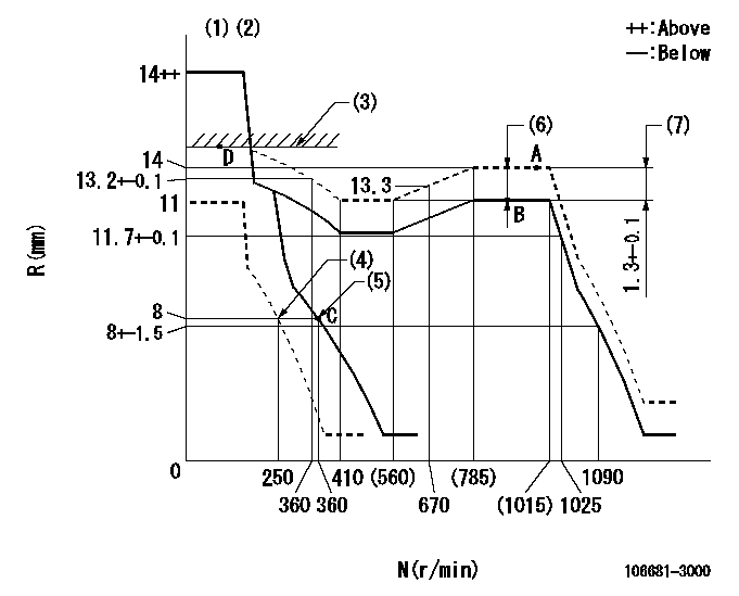
N:Pump speed
R:Rack position (mm)
(1)Notch fixed: K
(2)Tolerance for racks not indicated: +-0.05mm.
(3)RACK LIMIT
(4)Set idle sub-spring
(5)Main spring setting
(6)Boost compensator stroke: BCL
(7)Rack difference between N = N1 and N = N2
----------
K=14 BCL=1.8+-0.1mm N1=1000r/min N2=500r/min
----------
----------
K=14 BCL=1.8+-0.1mm N1=1000r/min N2=500r/min
----------
Speed control lever angle

F:Full speed
I:Idle
(1)Stopper bolt setting
----------
----------
a=(5deg)+-5deg b=(27deg)+-5deg
----------
----------
a=(5deg)+-5deg b=(27deg)+-5deg
Stop lever angle
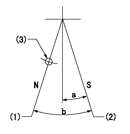
N:Pump normal
S:Stop the pump.
(1)Normal
(2)Pump speed aa and rack position bb (to be sealed at delivery)
(3)Use the hole above R = cc
----------
aa=0r/min bb=1-0.5mm cc=20mm
----------
a=10deg+-5deg b=70deg+-5deg
----------
aa=0r/min bb=1-0.5mm cc=20mm
----------
a=10deg+-5deg b=70deg+-5deg
Timing setting

(1)Pump vertical direction
(2)Coupling's key groove position at No 1 cylinder's beginning of injection
(3)B.T.D.C.: aa
(4)-
----------
aa=14deg
----------
a=(2deg)
----------
aa=14deg
----------
a=(2deg)
Information:
This Program must be administered as soon as possible. When reporting the repair, use "PI3147" as the Part Number, "7751" as the Group Number, "56" as the Warranty Claim Description Code and "T" as the SIMS Description Code. Exception: If the repair is done after failure, use "PI3147" as the Part Number, "7751" as the Group Number, "96" as the Warranty Claim Description Code, and "Z" as the SIMS Description Code.
Refer to your Warranty Bulletin for detailed information with regard to Product Improvement Programs.
Completion Date
November 30, 1998Termination Date
November 30, 1998Problem
Certain 3116 and 3126 2-Valve Engines built from January 28 through February 6, 1998 with CBS heads are suspect to have improper installation of the brass injector sleeve.
Affected Product
Model & Identification Number
3116 (2WG6414-6426 5EN01269, 5EN1270, 5EN1273-1280, 5EN1282 4KG7773-7795 4KG31268NM3029-3043 9ZR771-774 )
Parts Needed
1 - 1192940 Gasket* - 1193061 Sleeve*(as required)Action Required
See the attached procedure.
Owner Notification
U.S. and Canadian owners will receive the attached Owner Notification.
Service Claim Allowances
Parts Disposition
Handle the parts in accordance with your Warranty Bulletin on warranty parts handling.
MAKE EVERY EFFORT TO COMPLETE THIS PROGRAM AS SOON AS POSSIBLE.
Attach.(1-Owner Notification)(2-Rework Procedure)Copy Of Owner Notification For U.S. And Canadian Owners
Rework Procedure
1. Check to see if the head is supplied by CBS or Gosselies. The part number is located on the front of the head on the governor side beside the lifting eye, just above the front cover. In Marine applications, it is best viewed using a light to look between the expansion tank and heat exchanger.If it is a dot-matrix, then the head is from Gosselies. If the part number is stamped, then it is from CBS.
If the head is from Gosselies (dot-matrix part number), then the engine is good and no further work is needed.
If the head is from CBS (Stamped part number) then further inspection/rework is required.
2. If the head is from CBS, remove the valve cover.3. Using a sliding caliper, align the caliper vertically using the edge of the injector spring, measure and record the distance from the timing ledge on the injector to the top face of the head for each cylinder. This measurement will be in the range of 8.39 mm but can vary from engine to engine.4. If the variation from cylinder to cylinder on the same engine is less than 0.40 mm, then the engine is good. Re-install the valve cover. No further inspection is necessary.5. If the variation from cylinder to cylinder on the same engine is greater than 0.40 mm, recheck to verify measurements, if the difference is still greater than 0.40 mm, proceed to Step 6.6. Remove all (6) injectors. Using a depth gage with flat end and a 0.75 inch diameter steel ball dropped into the sleeve, check and record the distance from the top face of the head to the top of the steel ball. This measurement should be 2.583 0.18 inches (65.61 0.46 mm).7. Remove the injector sleeve on any cylinder that the measurement from step 6 is less than 2.565 inch (65.15 mm) and