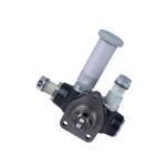
Information injection-pump assembly
BOSCH
9 400 617 453
9400617453
ZEXEL
106676-2611
1066762611
MITSUBISHI
ME440800
me440800
Rating:
Service parts 106676-2611 INJECTION-PUMP ASSEMBLY:
1.
_
7.
COUPLING PLATE
8.
_
9.
_
11.
Nozzle and Holder
ME440089
12.
Open Pre:MPa(Kqf/cm2)
15.7{160}/21.6{220}
14.
NOZZLE
Include in #1:
106676-2611
as INJECTION-PUMP ASSEMBLY
Cross reference number
BOSCH
9 400 617 453
9400617453
ZEXEL
106676-2611
1066762611
MITSUBISHI
ME440800
me440800
Zexel num
Bosch num
Firm num
Name
106676-2611
9 400 617 453
ME440800 MITSUBISHI
INJECTION-PUMP ASSEMBLY
6D24TL K 14CA INJECTION PUMP ASSY PE6P,6PD PE
6D24TL K 14CA INJECTION PUMP ASSY PE6P,6PD PE
Calibration Data:
Adjustment conditions
Test oil
1404 Test oil ISO4113 or {SAEJ967d}
1404 Test oil ISO4113 or {SAEJ967d}
Test oil temperature
degC
40
40
45
Nozzle and nozzle holder
105780-8140
Bosch type code
EF8511/9A
Nozzle
105780-0000
Bosch type code
DN12SD12T
Nozzle holder
105780-2080
Bosch type code
EF8511/9
Opening pressure
MPa
17.2
Opening pressure
kgf/cm2
175
Injection pipe
Outer diameter - inner diameter - length (mm) mm 8-3-600
Outer diameter - inner diameter - length (mm) mm 8-3-600
Overflow valve
131424-4420
Overflow valve opening pressure
kPa
157
157
157
Overflow valve opening pressure
kgf/cm2
1.6
1.6
1.6
Tester oil delivery pressure
kPa
157
157
157
Tester oil delivery pressure
kgf/cm2
1.6
1.6
1.6
Direction of rotation (viewed from drive side)
Right R
Right R
Injection timing adjustment
Direction of rotation (viewed from drive side)
Right R
Right R
Injection order
1-5-3-6-
2-4
Pre-stroke
mm
3.9
3.85
3.95
Beginning of injection position
Governor side NO.1
Governor side NO.1
Difference between angles 1
Cal 1-5 deg. 60 59.5 60.5
Cal 1-5 deg. 60 59.5 60.5
Difference between angles 2
Cal 1-3 deg. 120 119.5 120.5
Cal 1-3 deg. 120 119.5 120.5
Difference between angles 3
Cal 1-6 deg. 180 179.5 180.5
Cal 1-6 deg. 180 179.5 180.5
Difference between angles 4
Cyl.1-2 deg. 240 239.5 240.5
Cyl.1-2 deg. 240 239.5 240.5
Difference between angles 5
Cal 1-4 deg. 300 299.5 300.5
Cal 1-4 deg. 300 299.5 300.5
Injection quantity adjustment
Adjusting point
A
Rack position
12.1
Pump speed
r/min
1000
1000
1000
Average injection quantity
mm3/st.
155
152
158
Max. variation between cylinders
%
0
-3
3
Basic
*
Fixing the lever
*
Boost pressure
kPa
30
30
Boost pressure
mmHg
225
225
Injection quantity adjustment_02
Adjusting point
-
Rack position
8+-0.5
Pump speed
r/min
425
425
425
Average injection quantity
mm3/st.
16
13.4
18.6
Max. variation between cylinders
%
0
-15
15
Fixing the rack
*
Boost pressure
kPa
0
0
0
Boost pressure
mmHg
0
0
0
Remarks
Adjust only variation between cylinders; adjust governor according to governor specifications.
Adjust only variation between cylinders; adjust governor according to governor specifications.
Boost compensator adjustment
Pump speed
r/min
800
800
800
Rack position
R1-0.55
Boost pressure
kPa
7.3
4.6
10
Boost pressure
mmHg
55
35
75
Boost compensator adjustment_02
Pump speed
r/min
800
800
800
Rack position
R1(12.1)
Boost pressure
kPa
16.7
10
23.4
Boost pressure
mmHg
125
75
175
Test data Ex:
Governor adjustment
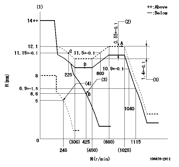
N:Pump speed
R:Rack position (mm)
(1)Notch fixed: K
(2)Boost compensator stroke
(3)Main spring setting
(4)Set idle sub-spring
(5)Rack difference between N = N1 and N = N2
----------
K=11 N1=1000r/min N2=375r/min
----------
----------
K=11 N1=1000r/min N2=375r/min
----------
Timer adjustment
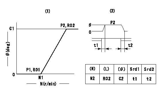
(1)Adjusting range
(2)Step response time
(N): Speed of the pump
(L): Load
(theta) Advance angle
(Srd1) Step response time 1
(Srd2) Step response time 2
1. Adjusting conditions for the variable timer
(1)Adjust the clearance between the pickup and the protrusion to L.
----------
L=1.5-0.2mm N2=800r/min C2=(10)deg t1=2.5--sec. t2=2.5--sec.
----------
N1=750++r/min P1=0kPa(0kgf/cm2) P2=392kPa(4kgf/cm2) C1=10+-0.3deg R01=0/4load R02=4/4load
----------
L=1.5-0.2mm N2=800r/min C2=(10)deg t1=2.5--sec. t2=2.5--sec.
----------
N1=750++r/min P1=0kPa(0kgf/cm2) P2=392kPa(4kgf/cm2) C1=10+-0.3deg R01=0/4load R02=4/4load
Speed control lever angle
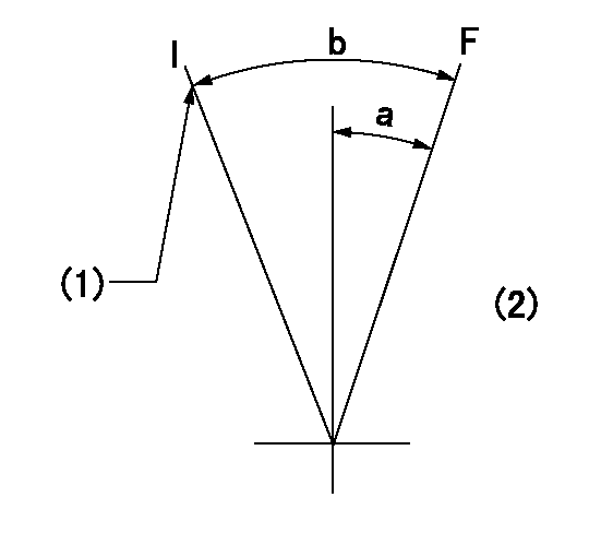
F:Full speed
I:Idle
(1)Stopper bolt setting
(2)Base lever only
----------
----------
a=(3deg)+-5deg b=(20deg)+-5deg
----------
----------
a=(3deg)+-5deg b=(20deg)+-5deg
Stop lever angle
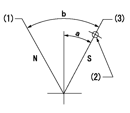
N:Pump normal
S:Stop the pump.
(1)Normal
(2)Rack position = aa, speed = bb (stamp at delivery)
(3)Use the hole above R = cc
----------
aa=1-0.5mm bb=0r/min cc=17mm
----------
a=35deg+-5deg b=70deg+-5deg
----------
aa=1-0.5mm bb=0r/min cc=17mm
----------
a=35deg+-5deg b=70deg+-5deg
0000001501 RACK SENSOR
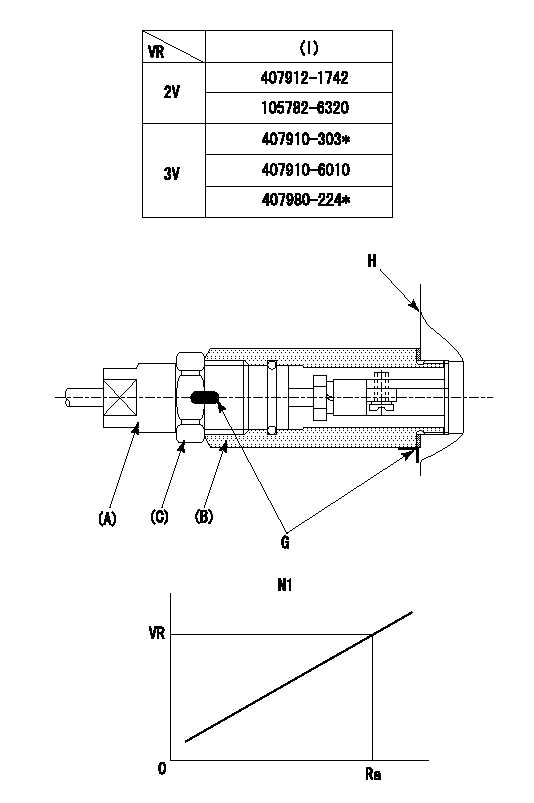
(VR) measurement voltage
(I) Part number of the control unit
(G) Apply red paint.
(H): End surface of the pump
1. Rack sensor adjustment (-0620)
(1)Fix the speed control lever at the full position
(2)Set the speed to N1 r/min.
(If the boost compensator is provided, apply boost pressure.)
(3)Adjust the bobbin (A) so that the rack sensor's output voltage is VR+-0.01.
(4)At that time, rack position must be Ra.
(5)Apply G at two places.
Connecting part between the joint (B) and the nut (F)
Connecting part between the joint (B) and the end surface of the pump (H)
----------
N1=1000r/min Ra=12.1mm
----------
----------
N1=1000r/min Ra=12.1mm
----------
0000001601 TAMPER PROOF

Tamperproofing-equipped boost compensator cover installation procedure
(A) After adjusting the boost compensator, tighten the bolts to remove the heads.
(1)Before adjusting the governor and the boost compensator, tighten the screw to the specified torque.
(Tightening torque T = T1 maximum)
(2)After adjusting the governor and the boost compensator, tighten to the specified torque to break off the bolt heads.
(Tightening torque T = T2 maximum)
----------
T1=2.5N-m(0.25kgf-m) T2=2.9~4.4N-m(0.3~0.45kgf-m)
----------
----------
T1=2.5N-m(0.25kgf-m) T2=2.9~4.4N-m(0.3~0.45kgf-m)
----------
Timing setting

(1)Pump vertical direction
(2)Coupling's key groove position at No 1 cylinder's beginning of injection
(3)B.T.D.C.: aa
(4)-
----------
aa=5deg
----------
a=(2deg)
----------
aa=5deg
----------
a=(2deg)
Information:
COOLING SYSTEM FLOW DIAGRAM
1. Cylinder head. 2. Aftercooler. 3. Water temperature regulator housing. 4. Coolant outlet from radiator. 5. Air compressor. 6. Bypass water line. 7. Coolant outlet to aftercooler. 8. Water manifold. 9. Coolant outlet to water manifold. 10. Cylinder block. 11. Oil cooler. 12. Coolant inlet to water pump. 13. Water pump. 14. Shunt line. 15. Radiator. 16. Vent line. 17. Upper chamber. 18. Bleed tube. 19. Lower chamber.This engine has a pressurized cooling system. Coolant is circulated by a belt driven, centrifugal type water pump. A water temperature regulator, located at the left front of the cylinder head, restricts coolant flow through the radiator until the coolant reaches operating temperature.The water pump has two outlets. One outlet directs coolant through a passage in the water temperature regulator housing to the aftercooler, to lower the temperature of inlet air in the inlet manifold. The other water outlet directs coolant through a water manifold in the side of the cylinder block, to cool engine lubricating oil. Coolant flows from the water manifold around the cylinder liners, into the cylinder head and around the precombustion chambers. Both streams of water join at the water temperature regulator.The water cooled air compressor receives coolant through a tube that is connected to the water manifold in the side of the cylinder block. Coolant returns through a tube from the air compressor head to the diesel engine cylinder head.Until the coolant reaches the temperature required to open the temperature regulator, coolant bypasses the radiator and flows directly back to the water pump.When the coolant reaches the temperature required to open the temperature regulator, coolant is then directed to the radiator lower chamber.The upper chamber of the radiator receives any air in the lower chamber by way of the bleed tube. Any air in the engine is vented to the radiator upper chamber thru the vent line. The shunt line from the upper chamber to the inlet of the water pump provides for rapid filling of the system.A pressure relief cap assembly is used to control the pressure in the cooling system, and prevents loss of coolant through the radiator overflow tube.Pressurizing the cooling system serves two purposes. First, it permits safe operation at coolant temperatures higher than the normal boiling point, providing a margin of cooling for intermittent peak loads. Secondly, it prevents cavitation in the water pump, and reduces the possibility of air or steam pockets forming in the coolant passages. Proper operation of the pressure relief cap assembly is essential. A pressure relief cap allows pressure (and some water, if the cooling system is too full) to escape when the pressure in the cooling system exceeds the capacity of the pressure cap. Loss of pressure will cause steam to form when coolant temperature is above the normal boiling point.Cooling System Components
Water Pump
The centrifugal-type water pump has two seals, one prevents leakage of water and the other prevents leakage of lubricant.An opening in the bottom of the pump housing allows any
Have questions with 106676-2611?
Group cross 106676-2611 ZEXEL
Mitsubishi
Mitsubishi
106676-2611
9 400 617 453
ME440800
INJECTION-PUMP ASSEMBLY
6D24TL
6D24TL
