Information injection-pump assembly
ZEXEL
106676-2610
1066762610
Rating:
Cross reference number
ZEXEL
106676-2610
1066762610
Zexel num
Bosch num
Firm num
Name
106676-2610
INJECTION-PUMP ASSEMBLY
Calibration Data:
Adjustment conditions
Test oil
1404 Test oil ISO4113 or {SAEJ967d}
1404 Test oil ISO4113 or {SAEJ967d}
Test oil temperature
degC
40
40
45
Nozzle and nozzle holder
105780-8140
Bosch type code
EF8511/9A
Nozzle
105780-0000
Bosch type code
DN12SD12T
Nozzle holder
105780-2080
Bosch type code
EF8511/9
Opening pressure
MPa
17.2
Opening pressure
kgf/cm2
175
Injection pipe
Outer diameter - inner diameter - length (mm) mm 8-3-600
Outer diameter - inner diameter - length (mm) mm 8-3-600
Overflow valve
131425-0220
Overflow valve opening pressure
kPa
157
157
157
Overflow valve opening pressure
kgf/cm2
1.6
1.6
1.6
Tester oil delivery pressure
kPa
157
157
157
Tester oil delivery pressure
kgf/cm2
1.6
1.6
1.6
Direction of rotation (viewed from drive side)
Right R
Right R
Injection timing adjustment
Direction of rotation (viewed from drive side)
Right R
Right R
Injection order
1-5-3-6-
2-4
Pre-stroke
mm
3.9
3.85
3.95
Beginning of injection position
Governor side NO.1
Governor side NO.1
Difference between angles 1
Cal 1-5 deg. 60 59.5 60.5
Cal 1-5 deg. 60 59.5 60.5
Difference between angles 2
Cal 1-3 deg. 120 119.5 120.5
Cal 1-3 deg. 120 119.5 120.5
Difference between angles 3
Cal 1-6 deg. 180 179.5 180.5
Cal 1-6 deg. 180 179.5 180.5
Difference between angles 4
Cyl.1-2 deg. 240 239.5 240.5
Cyl.1-2 deg. 240 239.5 240.5
Difference between angles 5
Cal 1-4 deg. 300 299.5 300.5
Cal 1-4 deg. 300 299.5 300.5
Injection quantity adjustment
Adjusting point
A
Rack position
12.1
Pump speed
r/min
1000
1000
1000
Average injection quantity
mm3/st.
155
152
158
Max. variation between cylinders
%
0
-3
3
Basic
*
Fixing the lever
*
Boost pressure
kPa
30
30
Boost pressure
mmHg
225
225
Injection quantity adjustment_02
Adjusting point
-
Rack position
8+-0.5
Pump speed
r/min
425
425
425
Average injection quantity
mm3/st.
16
13.4
18.6
Max. variation between cylinders
%
0
-15
15
Fixing the rack
*
Boost pressure
kPa
0
0
0
Boost pressure
mmHg
0
0
0
Remarks
Adjust only variation between cylinders; adjust governor according to governor specifications.
Adjust only variation between cylinders; adjust governor according to governor specifications.
Boost compensator adjustment
Pump speed
r/min
800
800
800
Rack position
R1-0.55
Boost pressure
kPa
7.3
4.6
10
Boost pressure
mmHg
55
35
75
Boost compensator adjustment_02
Pump speed
r/min
800
800
800
Rack position
R1(12.1)
Boost pressure
kPa
16.7
10
23.4
Boost pressure
mmHg
125
75
175
Test data Ex:
Governor adjustment
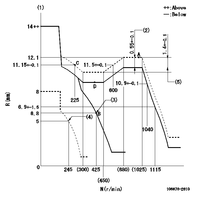
N:Pump speed
R:Rack position (mm)
(1)Notch fixed: K
(2)Boost compensator stroke
(3)Main spring setting
(4)Set idle sub-spring
(5)Rack difference between N = N1 and N = N2
----------
K=11 N1=1000r/min N2=375r/min
----------
----------
K=11 N1=1000r/min N2=375r/min
----------
Timer adjustment
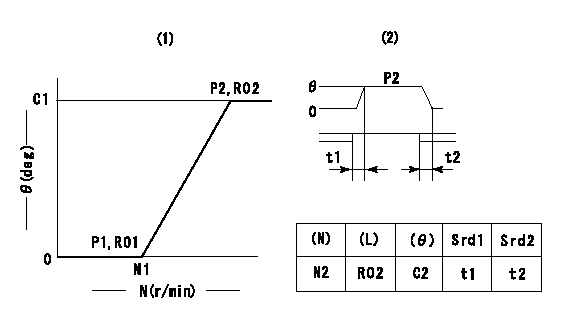
(1)Adjusting range
(2)Step response time
(N): Speed of the pump
(L): Load
(theta) Advance angle
(Srd1) Step response time 1
(Srd2) Step response time 2
1. Adjusting conditions for the variable timer
(1)Adjust the clearance between the pickup and the protrusion to L.
----------
L=1.5-0.2mm N2=800r/min C2=(10)deg t1=2.5--sec. t2=2.5--sec.
----------
N1=750++r/min P1=0kPa(0kgf/cm2) P2=392kPa(4kgf/cm2) C1=10+-0.3deg R01=0/4load R02=4/4load
----------
L=1.5-0.2mm N2=800r/min C2=(10)deg t1=2.5--sec. t2=2.5--sec.
----------
N1=750++r/min P1=0kPa(0kgf/cm2) P2=392kPa(4kgf/cm2) C1=10+-0.3deg R01=0/4load R02=4/4load
Speed control lever angle
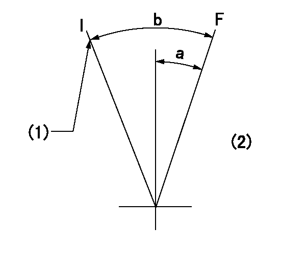
F:Full speed
I:Idle
(1)Stopper bolt setting
(2)Base lever only
----------
----------
a=(3deg)+-5deg b=(20deg)+-5deg
----------
----------
a=(3deg)+-5deg b=(20deg)+-5deg
Stop lever angle
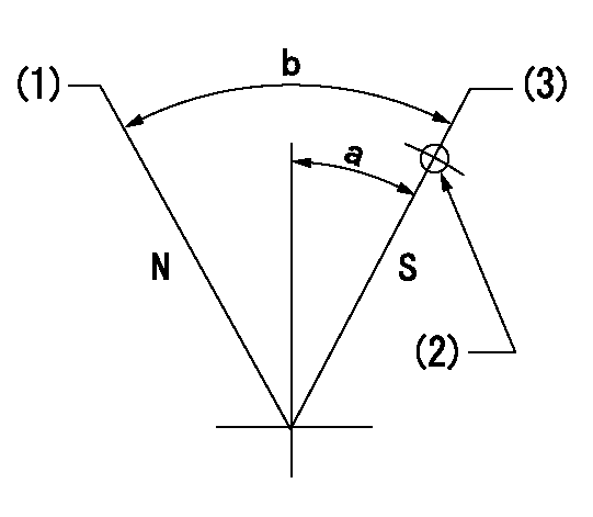
N:Pump normal
S:Stop the pump.
(1)Normal
(2)Rack position = aa, speed = bb (stamp at delivery)
(3)Use the hole above R = cc
----------
aa=1-0.5mm bb=0r/min cc=17mm
----------
a=35deg+-5deg b=70deg+-5deg
----------
aa=1-0.5mm bb=0r/min cc=17mm
----------
a=35deg+-5deg b=70deg+-5deg
0000001501 TAMPER PROOF

Tamperproofing-equipped boost compensator cover installation procedure
(A) After adjusting the boost compensator, tighten the bolts to remove the heads.
(1)Before adjusting the governor and the boost compensator, tighten the screw to the specified torque.
(Tightening torque T = T1 maximum)
(2)After adjusting the governor and the boost compensator, tighten to the specified torque to break off the bolt heads.
(Tightening torque T = T2 maximum)
----------
T1=2.5N-m(0.25kgf-m) T2=2.9~4.4N-m(0.3~0.45kgf-m)
----------
----------
T1=2.5N-m(0.25kgf-m) T2=2.9~4.4N-m(0.3~0.45kgf-m)
----------
0000001601 RACK SENSOR
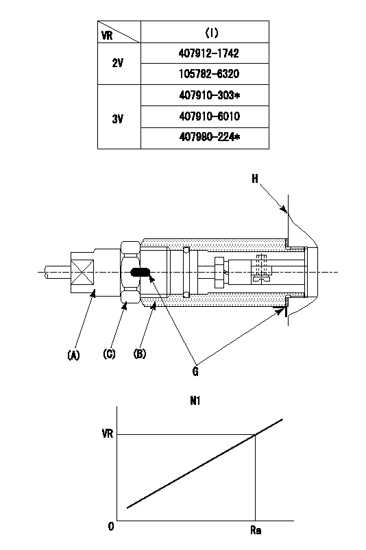
(VR) measurement voltage
(I) Part number of the control unit
(G) Apply red paint.
(H): End surface of the pump
1. Rack sensor adjustment (-0620)
(1)Fix the speed control lever at the full position
(2)Set the speed to N1 r/min.
(If the boost compensator is provided, apply boost pressure.)
(3)Adjust the bobbin (A) so that the rack sensor's output voltage is VR+-0.01.
(4)At that time, rack position must be Ra.
(5)Apply G at two places.
Connecting part between the joint (B) and the nut (F)
Connecting part between the joint (B) and the end surface of the pump (H)
----------
N1=1000r/min Ra=12.1mm
----------
----------
N1=1000r/min Ra=12.1mm
----------
Timing setting

(1)Pump vertical direction
(2)Coupling's key groove position at No 1 cylinder's beginning of injection
(3)B.T.D.C.: aa
(4)-
----------
aa=5deg
----------
a=(2deg)
----------
aa=5deg
----------
a=(2deg)
Information:
Illustration 21 shows the direction the rack moves when the fuel injector is receiving fuel.
Illustration 22 g01455811
Illustration 1 - Flowchart for the Air in Fuel Test (Test F)
Illustration 23 g01455812
Illustration 2 - Flowchart for the Air in Fuel Test (Test F)Fuel Injector Cranking Test (Test G)
Note: The fuel injector cranking test checks for worn out injectors by measuring the cranking rack.
Illustration 24 g01412134
(3) The rack control (4) The number one fuel injectorNote: Refer to Illustration 24 for the location of the rack control and the location of the number one injector.
Illustration 25 g01412115
Flowchart for the Fuel Injector Cranking Test (Test G)Fuel Shutoff Solenoid Test (Test H)
Note: The fuel shutoff solenoid test determines if the fuel shutoff solenoid and wiring harness are operating properly.
Illustration 26 g01412143
Flowchart for the Fuel Shutoff Solenoid Test (Test H)Fuel Ratio Control (FRC) Setting Test (Test I)
Note: The FRC setting test checks the FRC setting.
Illustration 27 g01412145
Flowchart for the Fuel Ratio Control (FRC) Setting Test (Test I)Governor Servo Retaining Ring Test (Test J)
Note: Do not run the engine during this test.Note: The governor servo retaining ring test checks for faulty internal parts of the governor.
Illustration 28 g01422811
(1) Paddle
Illustration 29 g01422821
(2) Clevis pin
Illustration 30 g01412147
Flowchart for the Governor Servo Retaining Ring Test (Test J)Fuel Transfer Pump Test (Test K)
Note: The fuel transfer pump test is a visual inspection of the fuel transfer pump components.
Illustration 31 g01412150
(1) Screen (2) Inlet check valve (3) Spring (4) Bolt (5) Piston (6) Outlet check valve (7) Freeze plug (8) Piston check valve (9) Passage (10) Tappet Assembly (11) CamNote: Refer to Illustration 31 for the location of the components for the fuel transfer pump.
Illustration 32 g01412149
Flowchart for the Fuel Transfer Pump Test (Test K)Fuel Ratio Control (FRC) Diaphragm Leak Test (Test L)
Note: The FRC diaphragm leak test checks for a leaking FRC diaphragm.
Illustration 33 g01412154
Flowchart for the Fuel Ratio Control (FRC) Diaphragm Leak Test (Test L)
Have questions with 106676-2610?
Group cross 106676-2610 ZEXEL
Mitsubishi
106676-2610
INJECTION-PUMP ASSEMBLY