Information injection-pump assembly
BOSCH
9 400 617 449
9400617449
ZEXEL
106676-2490
1066762490
MITSUBISHI
ME153460
me153460
Rating:
Cross reference number
BOSCH
9 400 617 449
9400617449
ZEXEL
106676-2490
1066762490
MITSUBISHI
ME153460
me153460
Zexel num
Bosch num
Firm num
Name
106676-2490
9 400 617 449
ME153460 MITSUBISHI
INJECTION-PUMP ASSEMBLY
6D24 K
6D24 K
Calibration Data:
Adjustment conditions
Test oil
1404 Test oil ISO4113 or {SAEJ967d}
1404 Test oil ISO4113 or {SAEJ967d}
Test oil temperature
degC
40
40
45
Nozzle and nozzle holder
105780-8250
Bosch type code
1 688 901 101
Nozzle
105780-0120
Bosch type code
1 688 901 990
Nozzle holder
105780-2190
Opening pressure
MPa
20.7
Opening pressure
kgf/cm2
211
Injection pipe
Outer diameter - inner diameter - length (mm) mm 8-3-600
Outer diameter - inner diameter - length (mm) mm 8-3-600
Overflow valve
131425-0220
Overflow valve opening pressure
kPa
157
123
191
Overflow valve opening pressure
kgf/cm2
1.6
1.25
1.95
Tester oil delivery pressure
kPa
255
255
255
Tester oil delivery pressure
kgf/cm2
2.6
2.6
2.6
Direction of rotation (viewed from drive side)
Right R
Right R
Injection timing adjustment
Direction of rotation (viewed from drive side)
Right R
Right R
Injection order
1-5-3-6-
2-4
Pre-stroke
mm
3.9
3.85
3.95
Beginning of injection position
Governor side NO.1
Governor side NO.1
Difference between angles 1
Cal 1-5 deg. 60 59.5 60.5
Cal 1-5 deg. 60 59.5 60.5
Difference between angles 2
Cal 1-3 deg. 120 119.5 120.5
Cal 1-3 deg. 120 119.5 120.5
Difference between angles 3
Cal 1-6 deg. 180 179.5 180.5
Cal 1-6 deg. 180 179.5 180.5
Difference between angles 4
Cyl.1-2 deg. 240 239.5 240.5
Cyl.1-2 deg. 240 239.5 240.5
Difference between angles 5
Cal 1-4 deg. 300 299.5 300.5
Cal 1-4 deg. 300 299.5 300.5
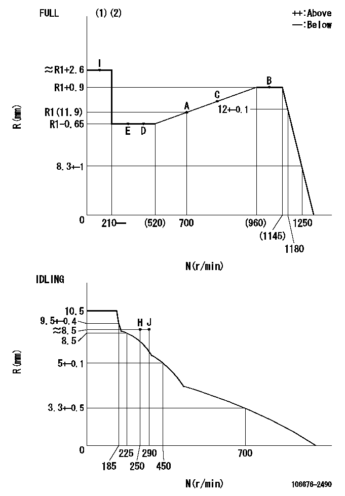
Injection quantity adjustment
Adjusting point
-
Rack position
11.9
Pump speed
r/min
700
700
700
Each cylinder's injection qty
mm3/st.
118.5
115.5
121.5
Basic
*
Fixing the rack
*
Standard for adjustment of the maximum variation between cylinders
*
Injection quantity adjustment_02
Adjusting point
Z
Rack position
8.5+-0.5
Pump speed
r/min
410
410
410
Each cylinder's injection qty
mm3/st.
15.8
13.4
18.2
Fixing the rack
*
Standard for adjustment of the maximum variation between cylinders
*
Injection quantity adjustment_03
Adjusting point
A
Rack position
R1(11.9)
Pump speed
r/min
700
700
700
Average injection quantity
mm3/st.
118.5
117.5
119.5
Basic
*
Fixing the lever
*
Injection quantity adjustment_04
Adjusting point
B
Rack position
R1+0.9
Pump speed
r/min
1100
1100
1100
Average injection quantity
mm3/st.
117
113
121
Fixing the lever
*
Injection quantity adjustment_05
Adjusting point
C
Rack position
(R1+0.7)
Pump speed
r/min
900
900
900
Average injection quantity
mm3/st.
124
120
128
Fixing the lever
*
Injection quantity adjustment_06
Adjusting point
D
Rack position
R1-0.65
Pump speed
r/min
500
500
500
Average injection quantity
mm3/st.
112.5
106.5
118.5
Fixing the lever
*
Timer adjustment
Pump speed
r/min
800--
Advance angle
deg.
0
0
0
Remarks
Start
Start
Timer adjustment_02
Pump speed
r/min
750
Advance angle
deg.
0.5
Timer adjustment_03
Pump speed
r/min
1100
Advance angle
deg.
2
1.5
2.5
Remarks
Finish
Finish
Test data Ex:
Governor adjustment
N:Pump speed
R:Rack position (mm)
(1)Torque cam stamping: T1
(2)Tolerance for racks not indicated: +-0.05mm.
----------
T1=AE41
----------
----------
T1=AE41
----------
Speed control lever angle
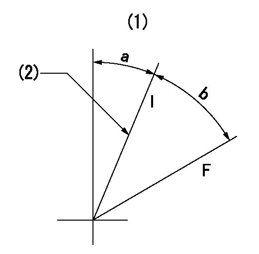
F:Full speed
I:Idle
(1)Viewed from feed pump side.
(2)Stopper bolt set position 'H'
----------
----------
a=30deg+-5deg b=(36.5deg)+-3deg
----------
----------
a=30deg+-5deg b=(36.5deg)+-3deg
Stop lever angle

N:Pump normal
S:Stop the pump.
(1)At pump speed aa and rack position bb, set the stopper bolt. (Confirm non-injection.)
(2)Normal engine position (Rack position corresponding to cc)
----------
aa=1100r/min bb=3.5+-0.3mm cc=18mm
----------
a=40deg+-5deg b=25.5deg+-5deg c=(31deg)+-5deg
----------
aa=1100r/min bb=3.5+-0.3mm cc=18mm
----------
a=40deg+-5deg b=25.5deg+-5deg c=(31deg)+-5deg
0000001501 MICRO SWITCH
Adjustment of the micro-switch
Adjust the bolt to obtain the following lever position when the micro-switch is ON.
(1)Speed N1
(2)Rack position Ra
----------
N1=325r/min Ra=7.6+-0.1mm
----------
----------
N1=325r/min Ra=7.6+-0.1mm
----------
Timing setting

(1)Pump vertical direction
(2)Coupling's key groove position at No 1 cylinder's beginning of injection
(3)B.T.D.C.: aa
(4)-
----------
aa=12deg
----------
a=(8deg)
----------
aa=12deg
----------
a=(8deg)
Information:
If there has been a previous repair, part age/hours will apply. Retain a copy of the previous repair invoice in the dealer's records for audit purposes, and specify repair date and machine hours in the "Additional Comments" section of the warranty claim.
Dealer to perform most economical repair.
Description____________________________SMCS Code___Hours
Wash___________________________________1091-074 ___0.2
Inner fender __________________________7252-010 ___0.2
R&I DPF _______________________________108F-010 ___1.2
program ECM - program DPF serial # ,
ASH reset, factory passwords __________1901-591 ___0.2
Test after Repair _____________________108F-030 ___0.2
This letter is to be performed during a recommended ash service as stated in Media number SEBU8087. Ash cleaning is a part of the recommended maintenance of the engine, customer is responsible for the labor required to remove and install the DPF.
PARTS DISPOSITION
Handle the parts in accordance with your Warranty Bulletin on warranty parts handling.
Rework Procedure
1. Wash debris from Diesel Particulate Filter (DPF) as necessary.
Image1.1.1
2. Remove the Fender (A): Loosen and remove the nuts and bolts from the fender of the truck. Retain the fender and fasteners for reuse. Refer to Image 1.1.1.
Image1.2.1
3. Remove the Step (B): Loosen and remove fasteners from the step of the truck. Retain the step and fasteners for reuse. Refer to Image 1.2.1.
Image1.3.1
Image1.3.2
4. Remove the Pipe Clamps: Loosen and remove clamps from the Inlet Pipe (C)& Outlet Pipe (D) of the DPF?s. Refer to Image 1.3.1 & Image 1.3.2
Image1.4.1
5. Remove tubes (E) and sensor box mounting bolts (F) to unplug sensor box connection. Refer to Image 1.4.1.
Image1.5.1
6. Remove DPF mounting bolts: Loosen and remove fasteners from the mounting of the DPF. Retain the mounting and fasteners for reuse. No jack will be used to hold DPF, DPF is supported by air tank brackets. Properly support DPF until it rests on the bracket. Refer to Image 1.5.1.
Image1.6.1
7. Slide the DPF forward and remove. Remove the CGI pipe (G) after the DPF has been removed. Refer to Image 1.6.1.
Image 1.7.1 shows the chassis after the welded DPF has been removed.
Image1.7.1
Image1.7.2
8. Install the Clamped DPF with mounting bolts (reuse the bolts). Install the new 330-4036 CGI Pipe for Group 1 & Group 2 with the 304-3048 Clamp. Check Inlet, Outlet and CGI pipes alignment, mounting brackets should be aligned with OEM brackets.
Refer OEM guidelines for connecting Inlet & CGI connections.
Image 1.7.2 shows the clamped DPF after it has been installed in the chassis.
9. Install the step and fender that were removed in Step 2 and Step 3.
10. Reset the engine ash model. Refer Media Number RENR9705.
11. Start the engine and use CAT ET to ensure that the status parameter Diesel Particulate Trap #1 Differential Pressure has a value greater than zero. Also ensure status parameters Diesel Particulate Trap #1 Intake Temperature, and Diesel Particulate Trap #1 Outlet Temperature show reasonable values and increase with the rising exhaust temperatures.
Have questions with 106676-2490?
Group cross 106676-2490 ZEXEL
Mitsubishi
Mitsubishi
Mitsubishi
Mitsubishi
106676-2490
9 400 617 449
ME153460
INJECTION-PUMP ASSEMBLY
6D24
6D24