Information injection-pump assembly
BOSCH
F 019 Z20 150
f019z20150
ZEXEL
106676-2463
1066762463
MITSUBISHI
ME442613
me442613
Rating:
Service parts 106676-2463 INJECTION-PUMP ASSEMBLY:
1.
_
7.
COUPLING PLATE
8.
_
9.
_
11.
Nozzle and Holder
12.
Open Pre:MPa(Kqf/cm2)
17.7(180)/21.6(220)

15.
NOZZLE SET
Include in #1:
106676-2463
as INJECTION-PUMP ASSEMBLY
Cross reference number
BOSCH
F 019 Z20 150
f019z20150
ZEXEL
106676-2463
1066762463
MITSUBISHI
ME442613
me442613
Zexel num
Bosch num
Firm num
Name
106676-2463
F 019 Z20 150
ME442613 MITSUBISHI
INJECTION-PUMP ASSEMBLY
6D24TC K 14CA INJECTION PUMP ASSY PE6P,6PD PE
6D24TC K 14CA INJECTION PUMP ASSY PE6P,6PD PE
Calibration Data:
Adjustment conditions
Test oil
1404 Test oil ISO4113 or {SAEJ967d}
1404 Test oil ISO4113 or {SAEJ967d}
Test oil temperature
degC
40
40
45
Nozzle and nozzle holder
105780-8140
Bosch type code
EF8511/9A
Nozzle
105780-0000
Bosch type code
DN12SD12T
Nozzle holder
105780-2080
Bosch type code
EF8511/9
Opening pressure
MPa
17.2
Opening pressure
kgf/cm2
175
Injection pipe
Outer diameter - inner diameter - length (mm) mm 8-3-600
Outer diameter - inner diameter - length (mm) mm 8-3-600
Overflow valve
131424-4620
Overflow valve opening pressure
kPa
255
221
289
Overflow valve opening pressure
kgf/cm2
2.6
2.25
2.95
Tester oil delivery pressure
kPa
255
255
255
Tester oil delivery pressure
kgf/cm2
2.6
2.6
2.6
Direction of rotation (viewed from drive side)
Right R
Right R
Injection timing adjustment
Direction of rotation (viewed from drive side)
Right R
Right R
Injection order
1-5-3-6-
2-4
Pre-stroke
mm
4.8
4.75
4.85
Beginning of injection position
Governor side NO.1
Governor side NO.1
Difference between angles 1
Cal 1-5 deg. 60 59.5 60.5
Cal 1-5 deg. 60 59.5 60.5
Difference between angles 2
Cal 1-3 deg. 120 119.5 120.5
Cal 1-3 deg. 120 119.5 120.5
Difference between angles 3
Cal 1-6 deg. 180 179.5 180.5
Cal 1-6 deg. 180 179.5 180.5
Difference between angles 4
Cyl.1-2 deg. 240 239.5 240.5
Cyl.1-2 deg. 240 239.5 240.5
Difference between angles 5
Cal 1-4 deg. 300 299.5 300.5
Cal 1-4 deg. 300 299.5 300.5
Injection quantity adjustment
Adjusting point
A
Rack position
10.5
Pump speed
r/min
900
900
900
Average injection quantity
mm3/st.
134
131
137
Max. variation between cylinders
%
0
-3
3
Basic
*
Fixing the lever
*
Injection quantity adjustment_02
Adjusting point
B
Rack position
6.5+-0.5
Pump speed
r/min
425
425
425
Average injection quantity
mm3/st.
12.5
9.9
15.1
Max. variation between cylinders
%
0
-15
15
Fixing the rack
*
Injection quantity adjustment_03
Adjusting point
C
Rack position
10.7++
Pump speed
r/min
100
100
100
Average injection quantity
mm3/st.
145
145
155
Fixing the lever
*
Rack limit
*
Timer adjustment
Pump speed
r/min
1200++
Advance angle
deg.
0
0
0
Remarks
Do not advance until starting N = 1200.
Do not advance until starting N = 1200.
Timer adjustment_02
Pump speed
r/min
-
Advance angle
deg.
2
2
2
Remarks
Measure the actual speed, stop
Measure the actual speed, stop
Test data Ex:
Governor adjustment
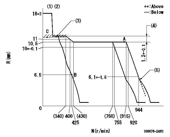
N:Pump speed
R:Rack position (mm)
(1)Notch fixed: K
(2)Tolerance for racks not indicated: +-0.05mm.
(3)RACK LIMIT
(4)Rack difference between N = N1 and N = N2
(5)Idle sub spring setting: L1.
----------
K=6 N1=900r/min N2=300r/min L1=4.7+-0.2mm
----------
----------
K=6 N1=900r/min N2=300r/min L1=4.7+-0.2mm
----------
Speed control lever angle
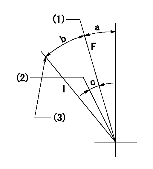
F:Full speed
I:Idle
(1)Set the pump speed at aa. ( At delivery )
(2)When pump speed set at bb
(3)Stopper bolt setting
----------
aa=920r/min bb=755r/min
----------
a=(2deg)+-5deg b=(15.5deg)+-5deg c=(5deg)+-5deg
----------
aa=920r/min bb=755r/min
----------
a=(2deg)+-5deg b=(15.5deg)+-5deg c=(5deg)+-5deg
Stop lever angle
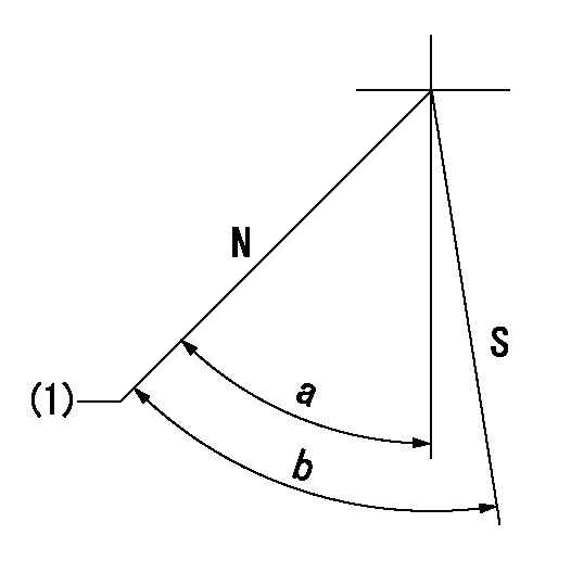
N:Pump normal
S:Stop the pump.
(1)Normal
----------
----------
a=43.5deg+-5deg b=53deg+-5deg
----------
----------
a=43.5deg+-5deg b=53deg+-5deg
Timing setting

(1)Pump vertical direction
(2)Coupling's key groove position at No 1 cylinder's beginning of injection
(3)B.T.D.C.: aa
(4)-
----------
aa=13deg
----------
a=(5deg)
----------
aa=13deg
----------
a=(5deg)
Information:
Image1
SERVICE CLAIM ALLOWANCES
Product smu/age whichever comes first Caterpillar Dealer Suggested Customer Suggested
Parts % Labor Hrs% Parts % Labor Hrs% Parts % Labor Hrs%
*******Group 1*******
0-500000 miles,
0-36 mo 100.0% 100.0% 0.0% 0.0% 0.0% 0.0%
This is a 6.0-hour job for Group 1
If the parts that are listed in the ACTION REQUIRED are on the engine, the engine has been previously updated and this Service Letter does not apply. Enter a claim against this service letter and charge 0.5 hours for the inspection time.
If the OEM CGI Flex line is replaced then it should be billed to your local OEM dealership as follows:
Cat Dealer Performs CGI Repair.
- Cat dealer purchases parts from Peterbilt / Kenworth dealer @ retail.
- Cat dealer performs repair (no charge to customer).
- Cat dealer files sublet invoice to Peterbilt / Kenworth dealer for parts (CAT will not increase part price to Peterbilt / Kenworth dealer) and labor reimbursement.
Invoice includes:
1) 17 digit VIN
2) Repair Order #
3) Vehicle mileage
4) Part pricing
5) Labor pricing
. Peterbilt / Kenworth dealer pays Cat dealer
. Peterbilt / Kenworth dealer files warranty claim (normal sublet) to Peterbilt / Kenworth
Peterbilt / Kenworth guarantees payment to Cat for the repairs performed.
Product smu/age whichever comes first Caterpillar Dealer Suggested Customer Suggested
Parts % Labor Hrs% Parts % Labor Hrs% Parts % Labor Hrs%
*******Group 2*******
0-500000 miles,
0-36 mo 100.0% 100.0% 0.0% 0.0% 0.0% 0.0%
This is a 6.0-hour job for Group 2
If the parts that are listed in the ACTION REQUIRED are on the engine, the engine has been previously updated and this Service Letter does not apply. Enter a claim against this service letter and charge 0.5 hours for the inspection time.
PARTS DISPOSITION
Handle the parts in accordance with your Warranty Bulletin on warranty parts handling.
Rework Procedure
Step 1:
Follow instructions outlined in REHS4803.
Step 2:
Attach Data Log of successful regen and attach Air Systems Verification Test report to the Warranty report and add Technician's CWS or SSO ID in the Technicians Name field of the "Warranty Report - User Information screen. See example on page 2 of REHS4803.
NOTE 1:
The seating of the heater wire to the ARD head is critical. There have been some cases of the heater wire interfering with the ARD head and not allowing it to seat properly. Refer to Image 1.1.1 for an example of proper seating.
If the heater wire hex interferes with the ARD head, use a file on the heater wire hex to allow proper seating (Image 1.1.2). DO NOT USE any cleaner after removing material from the hex as it can cause a heater failure. Usually less than 2mm reduction is necessary if proper seating does not take place.
Image1.1.1
Image1.1.2
Have questions with 106676-2463?
Group cross 106676-2463 ZEXEL
Mitsubishi
Mitsubishi
Mitsubishi
Mitsubishi
106676-2463
F 019 Z20 150
ME442613
INJECTION-PUMP ASSEMBLY
6D24TC
6D24TC