Information injection-pump assembly
ZEXEL
106676-2461
1066762461
Rating:
Cross reference number
ZEXEL
106676-2461
1066762461
Zexel num
Bosch num
Firm num
Name
106676-2461
INJECTION-PUMP ASSEMBLY
Calibration Data:
Adjustment conditions
Test oil
1404 Test oil ISO4113 or {SAEJ967d}
1404 Test oil ISO4113 or {SAEJ967d}
Test oil temperature
degC
40
40
45
Nozzle and nozzle holder
105780-8140
Bosch type code
EF8511/9A
Nozzle
105780-0000
Bosch type code
DN12SD12T
Nozzle holder
105780-2080
Bosch type code
EF8511/9
Opening pressure
MPa
17.2
Opening pressure
kgf/cm2
175
Injection pipe
Outer diameter - inner diameter - length (mm) mm 8-3-600
Outer diameter - inner diameter - length (mm) mm 8-3-600
Overflow valve
131424-4620
Overflow valve opening pressure
kPa
255
255
255
Overflow valve opening pressure
kgf/cm2
2.6
2.6
2.6
Tester oil delivery pressure
kPa
255
255
255
Tester oil delivery pressure
kgf/cm2
2.6
2.6
2.6
Direction of rotation (viewed from drive side)
Right R
Right R
Injection timing adjustment
Direction of rotation (viewed from drive side)
Right R
Right R
Injection order
1-5-3-6-
2-4
Pre-stroke
mm
4.8
4.75
4.85
Beginning of injection position
Governor side NO.1
Governor side NO.1
Difference between angles 1
Cal 1-5 deg. 60 59.5 60.5
Cal 1-5 deg. 60 59.5 60.5
Difference between angles 2
Cal 1-3 deg. 120 119.5 120.5
Cal 1-3 deg. 120 119.5 120.5
Difference between angles 3
Cal 1-6 deg. 180 179.5 180.5
Cal 1-6 deg. 180 179.5 180.5
Difference between angles 4
Cyl.1-2 deg. 240 239.5 240.5
Cyl.1-2 deg. 240 239.5 240.5
Difference between angles 5
Cal 1-4 deg. 300 299.5 300.5
Cal 1-4 deg. 300 299.5 300.5
Injection quantity adjustment
Adjusting point
A
Rack position
10.5
Pump speed
r/min
900
900
900
Average injection quantity
mm3/st.
134
131
137
Max. variation between cylinders
%
0
-3
3
Basic
*
Fixing the lever
*
Injection quantity adjustment_02
Adjusting point
B
Rack position
6.5+-0.5
Pump speed
r/min
425
425
425
Average injection quantity
mm3/st.
12.5
9.9
15.1
Max. variation between cylinders
%
0
-15
15
Fixing the rack
*
Injection quantity adjustment_03
Adjusting point
C
Rack position
10.7++
Pump speed
r/min
100
100
100
Average injection quantity
mm3/st.
145
145
155
Fixing the lever
*
Rack limit
*
Timer adjustment
Pump speed
r/min
1200++
Advance angle
deg.
0
0
0
Remarks
Do not advance until starting N = 1200.
Do not advance until starting N = 1200.
Timer adjustment_02
Pump speed
r/min
1200
Advance angle
deg.
0.5
Timer adjustment_03
Pump speed
r/min
-
Advance angle
deg.
2
2
2
Remarks
Measure the actual speed, stop
Measure the actual speed, stop
Test data Ex:
Governor adjustment
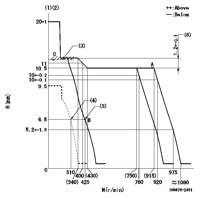
N:Pump speed
R:Rack position (mm)
(1)Notch fixed: K
(2)Tolerance for racks not indicated: +-0.05mm.
(3)RACK LIMIT
(4)Set idle sub-spring
(5)Main spring setting
(6)Rack difference between N = N1 and N = N2
----------
K=8 N1=900r/min N2=300r/min
----------
----------
K=8 N1=900r/min N2=300r/min
----------
Speed control lever angle
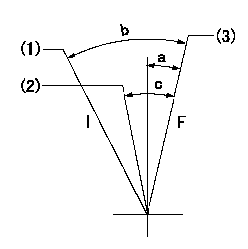
F:Full speed
I:Idle
(1)Stopper bolt setting
(2)Set the pump speed at aa
(3)Set the pump speed at bb.
----------
aa=760r/min bb=920r/min
----------
a=(1deg)+-5deg b=(19deg)+-5deg c=(6deg)+-5deg
----------
aa=760r/min bb=920r/min
----------
a=(1deg)+-5deg b=(19deg)+-5deg c=(6deg)+-5deg
Stop lever angle
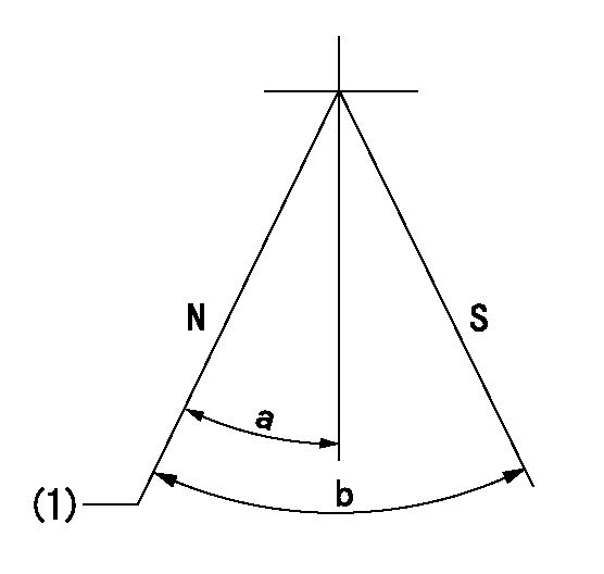
N:Pump normal
S:Stop the pump.
(1)Normal
----------
----------
a=43.5deg+-5deg b=53deg+-5deg
----------
----------
a=43.5deg+-5deg b=53deg+-5deg
Timing setting

(1)Pump vertical direction
(2)Coupling's key groove position at No 1 cylinder's beginning of injection
(3)B.T.D.C.: aa
(4)-
----------
aa=13deg
----------
a=(7deg)
----------
aa=13deg
----------
a=(7deg)
Information:
Image1.5.1
2. Use 4 new grommets (MCI part number 97-2246-00002 (Dealer Order)) per bus. Grommets are to be installed between the clamp and chassis frame at same location as originals.
3. Clean existing exhaust inlet pipe with wire brush for reuse. Install new Exhaust clamps (Dealer Order).
4. Clean existing exhaust Outlet pipe with wire brush for reuse. Install new Exhaust clamps (Dealer Order).
5. Use a floor jack or transmission jack with CCRT properly secured to lift into place. Place a pipe clamp loosely over the inlet socket. Use the jack to raise the CCRT assembly into position. Insert exhaust pipe elbow into inlet socket. Tighten the clamp bolt to a torque of approximately 50 lb ft. Refer image 1.5.1.
Image1.6.1
6. Provide adequate clearance to Pro Heat exhaust pipe. Mounting brackets will have 1/2 inch slotted bolt holes. Orient to provide needed clearance. Refer image 1.6.1.
Image1.7.1
7. Install Thermocouple.
- Apply a thin coat of anti-seize to the threads of the Male Run Tee and thread it into the boss on the CCRT inlet. Image 1.7.1 shows a completed installation.
- All the parts used from Step 7 to Step 10 are included in the 219-7990 Installation Kit.
Image1.8.1
8. Insert the reducer fitting into the Tee fitting in line with the boss (Image 1.8.1). Tighten the lock nut (also use the Lock Washer) on the Tee until it is finger tight and then tighten it 1 1/4 turns with a 9/16" wrench.
Image1.9.1
9. Insert the thermocouple into the reducer as far as it will go, then pull it back 1/4 inch (Image 1.9.1). Tighten the lock nut finger tight and then tighten 1 1/4 turns with a 7/16" wrench. If necessary, the thermocouple may be bent ONCE to avoid any interference. Do not bend the thermocouple past 90 degrees.
NOTE. JM instructions instruct to insert probe and withdraw one inch. For this installation, insert probe and withdraw 1/4 inch to allow accurate temperature measurement of the exhaust.
Image1.10.1
10. Insert the copper tubing into the fitting on the Tee that is at a 90 degree angle to the boss (Image 1.10.1). Tighten the fitting on the Tee until it is finger tight. Then tighten it 1 1/4 turns with a 9/16" wrench.
Image1.11.1
Image1.11.2
11. Route the cable and copper tube and the secure cable with 6K0806 Cable Straps as shown. It is important to use these cable straps so the tube and cable are oriented in a way that they do not rub against the frame.
Install P brackets every two to three feet as needed. Refer in Image 1.11.2.
12. Install 271-6537 CCRT Diagnostic Module using Bolts (4M5282), Washers (8T4205), nut (6V8185) and Lock Washer (3B4504). Use carbide tip drill bit for drilling in stainless steel.
Image1.13.1
13. Install 282-0031 Remote Display monitor lights along with dealer fabricated Remote Display Bracket. Use self tapping screws (90064A581), Splice (1364877), Washer (4B4274), Locknut (031049) and screw (4B1232).
Image1.14.1
14. Connect power using 3A Fuse.
15. Install existing Pin insulator on the weatherpack plug that connects to the OEM harness at the firewall that provides power to the CRT module.
16. Download
Have questions with 106676-2461?
Group cross 106676-2461 ZEXEL
Mitsubishi
Mitsubishi
Mitsubishi
106676-2461
INJECTION-PUMP ASSEMBLY