Information injection-pump assembly
ZEXEL
106676-2440
1066762440
Rating:
Cross reference number
ZEXEL
106676-2440
1066762440
Zexel num
Bosch num
Firm num
Name
106676-2440
INJECTION-PUMP ASSEMBLY
Calibration Data:
Adjustment conditions
Test oil
1404 Test oil ISO4113 or {SAEJ967d}
1404 Test oil ISO4113 or {SAEJ967d}
Test oil temperature
degC
40
40
45
Nozzle and nozzle holder
105780-8250
Bosch type code
1 688 901 101
Nozzle
105780-0120
Bosch type code
1 688 901 990
Nozzle holder
105780-2190
Opening pressure
MPa
20.7
Opening pressure
kgf/cm2
211
Injection pipe
Outer diameter - inner diameter - length (mm) mm 8-3-600
Outer diameter - inner diameter - length (mm) mm 8-3-600
Overflow valve
131425-0220
Overflow valve opening pressure
kPa
157
123
191
Overflow valve opening pressure
kgf/cm2
1.6
1.25
1.95
Tester oil delivery pressure
kPa
255
255
255
Tester oil delivery pressure
kgf/cm2
2.6
2.6
2.6
Direction of rotation (viewed from drive side)
Right R
Right R
Injection timing adjustment
Direction of rotation (viewed from drive side)
Right R
Right R
Injection order
1-5-3-6-
2-4
Pre-stroke
mm
3.9
3.85
3.95
Beginning of injection position
Governor side NO.1
Governor side NO.1
Difference between angles 1
Cal 1-5 deg. 60 59.5 60.5
Cal 1-5 deg. 60 59.5 60.5
Difference between angles 2
Cal 1-3 deg. 120 119.5 120.5
Cal 1-3 deg. 120 119.5 120.5
Difference between angles 3
Cal 1-6 deg. 180 179.5 180.5
Cal 1-6 deg. 180 179.5 180.5
Difference between angles 4
Cyl.1-2 deg. 240 239.5 240.5
Cyl.1-2 deg. 240 239.5 240.5
Difference between angles 5
Cal 1-4 deg. 300 299.5 300.5
Cal 1-4 deg. 300 299.5 300.5
Injection quantity adjustment
Adjusting point
-
Rack position
12
Pump speed
r/min
700
700
700
Each cylinder's injection qty
mm3/st.
131
127.7
134.3
Basic
*
Fixing the rack
*
Standard for adjustment of the maximum variation between cylinders
*
Injection quantity adjustment_02
Adjusting point
Z
Rack position
8+-0.5
Pump speed
r/min
410
410
410
Each cylinder's injection qty
mm3/st.
21
17.8
24.2
Fixing the rack
*
Standard for adjustment of the maximum variation between cylinders
*
Injection quantity adjustment_03
Adjusting point
A
Rack position
R1(12)
Pump speed
r/min
700
700
700
Average injection quantity
mm3/st.
131
130
132
Basic
*
Fixing the lever
*
Boost pressure
kPa
24.7
24.7
Boost pressure
mmHg
185
185
Injection quantity adjustment_04
Adjusting point
B
Rack position
R1+1.15
Pump speed
r/min
1100
1100
1100
Average injection quantity
mm3/st.
132
128
136
Fixing the lever
*
Boost pressure
kPa
24.7
24.7
Boost pressure
mmHg
185
185
Injection quantity adjustment_05
Adjusting point
D
Rack position
(R1-0.65
)
Pump speed
r/min
500
500
500
Average injection quantity
mm3/st.
129
123
135
Fixing the lever
*
Boost pressure
kPa
24.7
24.7
Boost pressure
mmHg
185
185
Boost compensator adjustment
Pump speed
r/min
300
300
300
Rack position
R2-0.85
Boost pressure
kPa
7.3
6
8.6
Boost pressure
mmHg
55
45
65
Boost compensator adjustment_02
Pump speed
r/min
300
300
300
Rack position
R2(R1-1.
05)
Boost pressure
kPa
11.3
11.3
11.3
Boost pressure
mmHg
85
85
85
Timer adjustment
Pump speed
r/min
750--
Advance angle
deg.
0
0
0
Remarks
Start
Start
Timer adjustment_02
Pump speed
r/min
700
Advance angle
deg.
0.5
Timer adjustment_03
Pump speed
r/min
1100
Advance angle
deg.
2
1.5
2.5
Remarks
Finish
Finish
Test data Ex:
Governor adjustment
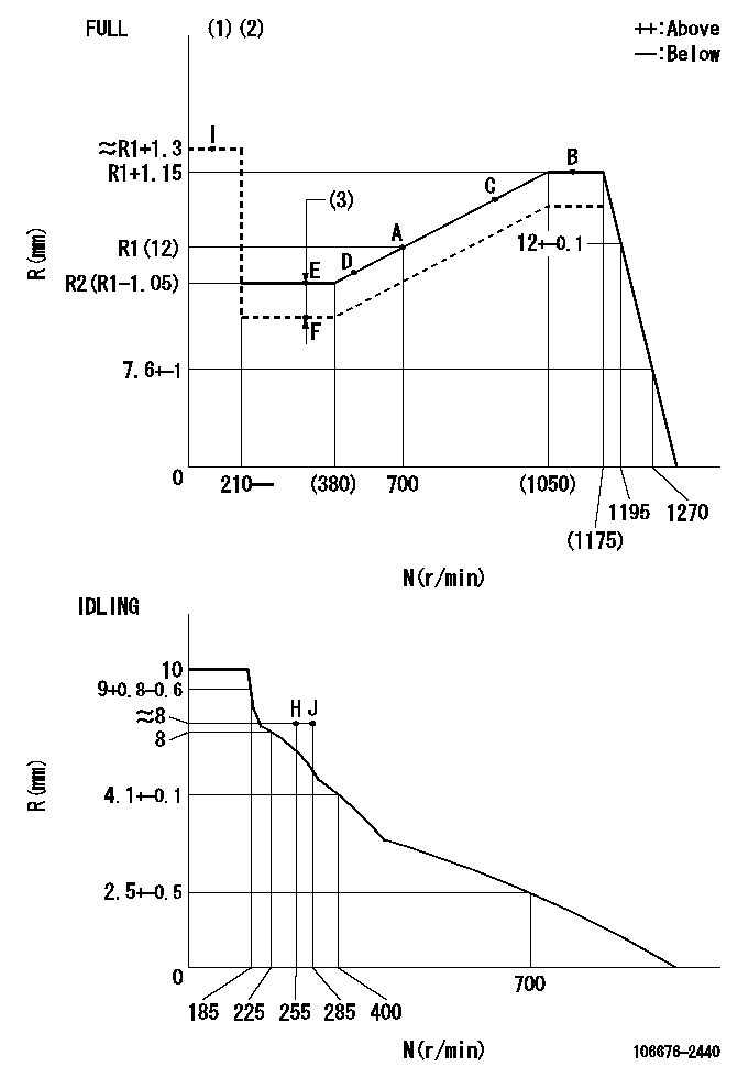
N:Pump speed
R:Rack position (mm)
(1)Torque cam stamping: T1
(2)Tolerance for racks not indicated: +-0.05mm.
(3)Boost compensator stroke: BCL
----------
T1=AG53 BCL=0.85+-0.1mm
----------
----------
T1=AG53 BCL=0.85+-0.1mm
----------
Speed control lever angle
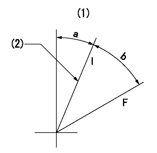
F:Full speed
I:Idle
(1)Viewed from feed pump side.
(2)Stopper bolt set position 'H'
----------
----------
a=32.5deg+-5deg b=40deg+-3deg
----------
----------
a=32.5deg+-5deg b=40deg+-3deg
Stop lever angle

N:Pump normal
S:Stop the pump.
(1)At pump speed aa and rack position bb, set the stopper bolt. (Confirm non-injection.)
(2)Normal engine position (Rack position corresponding to cc)
(3)Use the hole above R = dd
----------
aa=1100r/min bb=3.5+-0.3mm cc=18mm dd=33.5mm
----------
a=40deg+-5deg b=25.5deg+-5deg c=(31deg)+-5deg
----------
aa=1100r/min bb=3.5+-0.3mm cc=18mm dd=33.5mm
----------
a=40deg+-5deg b=25.5deg+-5deg c=(31deg)+-5deg
Timing setting

(1)Pump vertical direction
(2)Coupling's key groove position at No 1 cylinder's beginning of injection
(3)B.T.D.C.: aa
(4)-
----------
aa=10deg
----------
a=(2deg)
----------
aa=10deg
----------
a=(2deg)
Information:
face="Courier New" size=-1>0.0% 0.0% 0.0%
This is a 5.0-hour job for Group 2
Product smu/age whichever comes first Caterpillar Dealer Suggested Customer Suggested
Parts % Labor Hrs% Parts % Labor Hrs% Parts % Labor Hrs%
*******Group 3*******
0-3000 hrs,
0-24 mo 100.0% 100.0% 0.0% 0.0% 0.0% 0.0%
This is a 5.0-hour job for Group 3
Product smu/age whichever comes first Caterpillar Dealer Suggested Customer Suggested
Parts % Labor Hrs% Parts % Labor Hrs% Parts % Labor Hrs%
*******Group 4*******
0-3000 hrs,
0-24 mo 100.0% 100.0% 0.0% 0.0% 0.0% 0.0%
This is a 5.0-hour job for Group 4
Product smu/age whichever comes first Caterpillar Dealer Suggested Customer Suggested
Parts % Labor Hrs% Parts % Labor Hrs% Parts % Labor Hrs%
*******Group 5*******
0-3000 hrs,
0-24 mo 100.0% 100.0% 0.0% 0.0% 0.0% 0.0%
This is a 5.0-hour job for Group 5
PARTS DISPOSITION
Handle the parts in accordance with your Warranty Bulletin on warranty parts handling.
Rework Procedure
Engine Injector Change:
First identify which level of injector you currently have in your engine and establish which is the latest injector to replace it.
To remove and replace the injectors use the following Disassembly and Assembly Instructions.
C6.6 Caterpillar Industrial Engines: Install and Remove procedure RENR9722
C6.6 Caterpillar Built Machine: Install and Remove procedure KENR6081
Engine Reflash:
To update the flash file follow the procedure below. Refer to TMI or SISWeb for the latest flash file.
Tools Required:
PC or laptop with CAT ET installed and licensed (Version 2007A minimum) Communication Adaptor with diagnostic connector.
Flash File procedure:
Process:
1. Download the correct flash file from TMI or SISWeb.
2. Save the correct flash file to your local hard drive.
3. Connect to the ECM using Service Tool (CAT ET).
4. Make sure the ECM is powered up (Check that Red light on Comm. Adaptor is illuminated).
5. Go to "Winflash" or "Flash Memory".
6. CAT ET re-connect to the ECM.
7. Using the browse function in the top right hand corner, select the new flash file previously saved to hard drive.
8. Select "Begin Flash" (bottom right hand corner).
9. Once Flashing is complete select "CAT ET".
10. The Personality Module Mismatch should appear, select the ok button.
11. The factory password screen should now appear.
12. Use https://fps.cat.com to obtain factory passwords.
13. Enter Factory Passwords.
14. CAT ET High Level Configuration screen should be displayed.
15. Re-flash complete.
Have questions with 106676-2440?
Group cross 106676-2440 ZEXEL
Mitsubishi
106676-2440
INJECTION-PUMP ASSEMBLY