Information injection-pump assembly
BOSCH
9 400 617 443
9400617443
ZEXEL
106676-2361
1066762361
MITSUBISHI
ME158888
me158888

Rating:
Cross reference number
BOSCH
9 400 617 443
9400617443
ZEXEL
106676-2361
1066762361
MITSUBISHI
ME158888
me158888
Zexel num
Bosch num
Firm num
Name
106676-2361
9 400 617 443
ME158888 MITSUBISHI
INJECTION-PUMP ASSEMBLY
6D24T K
6D24T K
Calibration Data:
Adjustment conditions
Test oil
1404 Test oil ISO4113 or {SAEJ967d}
1404 Test oil ISO4113 or {SAEJ967d}
Test oil temperature
degC
40
40
45
Nozzle and nozzle holder
105780-8140
Bosch type code
EF8511/9A
Nozzle
105780-0000
Bosch type code
DN12SD12T
Nozzle holder
105780-2080
Bosch type code
EF8511/9
Opening pressure
MPa
17.2
Opening pressure
kgf/cm2
175
Injection pipe
Outer diameter - inner diameter - length (mm) mm 8-3-600
Outer diameter - inner diameter - length (mm) mm 8-3-600
Overflow valve
131424-4620
Overflow valve opening pressure
kPa
255
255
255
Overflow valve opening pressure
kgf/cm2
2.6
2.6
2.6
Tester oil delivery pressure
kPa
157
157
157
Tester oil delivery pressure
kgf/cm2
1.6
1.6
1.6
Direction of rotation (viewed from drive side)
Right R
Right R
Injection timing adjustment
Direction of rotation (viewed from drive side)
Right R
Right R
Injection order
1-5-3-6-
2-4
Pre-stroke
mm
4.8
4.75
4.85
Beginning of injection position
Governor side NO.1
Governor side NO.1
Difference between angles 1
Cal 1-5 deg. 60 59.5 60.5
Cal 1-5 deg. 60 59.5 60.5
Difference between angles 2
Cal 1-3 deg. 120 119.5 120.5
Cal 1-3 deg. 120 119.5 120.5
Difference between angles 3
Cal 1-6 deg. 180 179.5 180.5
Cal 1-6 deg. 180 179.5 180.5
Difference between angles 4
Cyl.1-2 deg. 240 239.5 240.5
Cyl.1-2 deg. 240 239.5 240.5
Difference between angles 5
Cal 1-4 deg. 300 299.5 300.5
Cal 1-4 deg. 300 299.5 300.5
Injection quantity adjustment
Adjusting point
A
Rack position
8.9
Pump speed
r/min
1000
1000
1000
Average injection quantity
mm3/st.
123
120
126
Max. variation between cylinders
%
0
-3
3
Basic
*
Fixing the lever
*
Boost pressure
kPa
30.7
30.7
Boost pressure
mmHg
230
230
Injection quantity adjustment_02
Adjusting point
B
Rack position
4.4+-0.5
Pump speed
r/min
425
425
425
Average injection quantity
mm3/st.
9.5
6.9
12.1
Max. variation between cylinders
%
0
-15
15
Fixing the rack
*
Boost pressure
kPa
0
0
0
Boost pressure
mmHg
0
0
0
Injection quantity adjustment_03
Adjusting point
D
Rack position
10.2++
Pump speed
r/min
100
100
100
Average injection quantity
mm3/st.
145
135
155
Fixing the lever
*
Boost pressure
kPa
0
0
0
Boost pressure
mmHg
0
0
0
Rack limit
*
Boost compensator adjustment
Pump speed
r/min
700
700
700
Rack position
R1-1.25
Boost pressure
kPa
4
2.7
5.3
Boost pressure
mmHg
30
20
40
Boost compensator adjustment_02
Pump speed
r/min
700
700
700
Rack position
R1(8.9)
Boost pressure
kPa
17.3
10.6
24
Boost pressure
mmHg
130
80
180
Timer adjustment
Pump speed
r/min
0
Advance angle
deg.
2.5
2
3
Timer adjustment_02
Pump speed
r/min
300
Advance angle
deg.
2.5
2
3
Remarks
Start
Start
Timer adjustment_03
Pump speed
r/min
-
Advance angle
deg.
0
0
0
Remarks
Measure the actual speed, stop
Measure the actual speed, stop
Test data Ex:
Governor adjustment
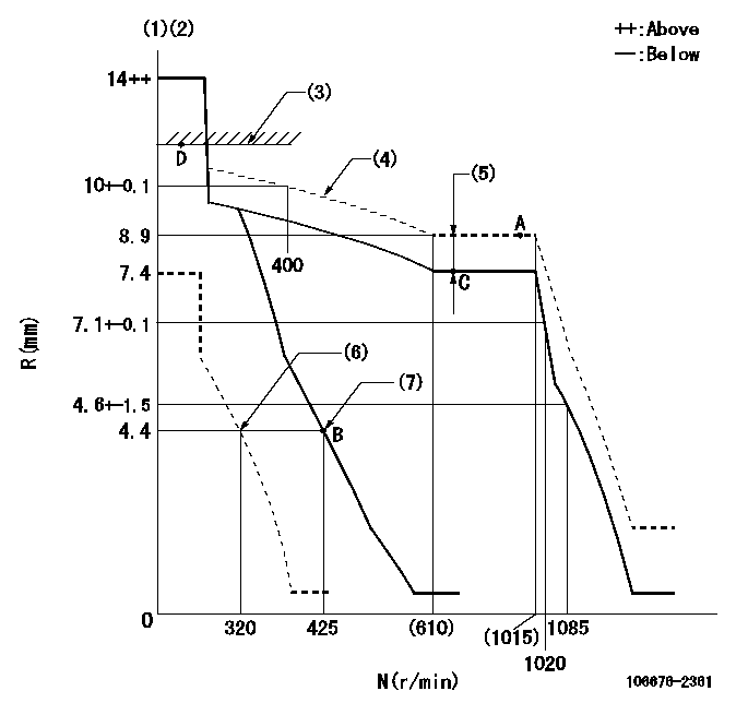
N:Pump speed
R:Rack position (mm)
(1)Notch fixed: K
(2)Tolerance for racks not indicated: +-0.05mm.
(3)RACK LIMIT
(4)The torque control spring must does not have a set force.
(5)Boost compensator stroke: BCL
(6)Set idle sub-spring
(7)Main spring setting
----------
K=12 BCL=1.25+-0.1mm
----------
----------
K=12 BCL=1.25+-0.1mm
----------
Speed control lever angle
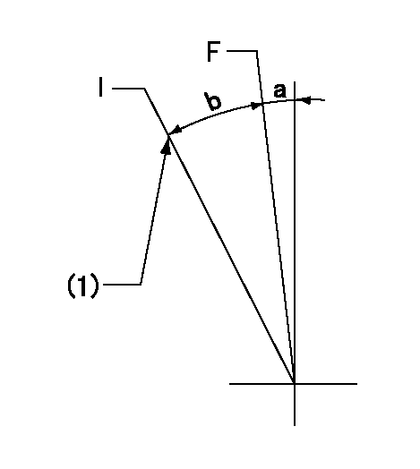
F:Full speed
I:Idle
(1)Stopper bolt setting
----------
----------
a=(4deg)+-5deg b=(14deg)+-5deg
----------
----------
a=(4deg)+-5deg b=(14deg)+-5deg
Stop lever angle
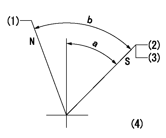
N:Pump normal
S:Stop the pump.
(1)Set the outer screw where it contacts the inside (seal at delivery)
(2)Pump speed aa and rack position bb (to be sealed at delivery)
(3)Stopper bolt setting
(4)No return spring
----------
aa=0r/min bb=1-0.5mm
----------
a=55deg+-5deg b=70deg+-5deg
----------
aa=0r/min bb=1-0.5mm
----------
a=55deg+-5deg b=70deg+-5deg
0000001501 TAMPER PROOF

Tamperproofing-equipped boost compensator cover installation procedure
(A) After adjusting the boost compensator, tighten the bolts to remove the heads.
(1)Before adjusting the governor and the boost compensator, tighten the screw to the specified torque.
(Tightening torque T = T1 maximum)
(2)After adjusting the governor and the boost compensator, tighten to the specified torque to break off the bolt heads.
(Tightening torque T = T2 maximum)
----------
T1=2.5N-m(0.25kgf-m) T2=2.9~4.4N-m(0.3~0.45kgf-m)
----------
----------
T1=2.5N-m(0.25kgf-m) T2=2.9~4.4N-m(0.3~0.45kgf-m)
----------
Timing setting

(1)Pump vertical direction
(2)Coupling's key groove position at No 1 cylinder's beginning of injection
(3)B.T.D.C.: aa
(4)-
----------
aa=12deg
----------
a=(6deg)
----------
aa=12deg
----------
a=(6deg)
Information:
PARTS NEEDED
Qty
Part Number Description
2 6V8260 SEAL-O-RING
1 10R6350 PUMP GP-FUEL
1 2923739 TUBE AS-FUEL
1 2923740 TUBE AS-FUEL
ACTION REQUIRED
This procedure only applies to engines with less than 250 hours.
Step 1: Verify oil level on the dipstick gage is at the full mark after engine has been shut off for 15 minutes. Adjust oil level if necessary and reconfirm oil level is at the full mark on gage before procedeing to Step 2.
Step 2: Use Cat Electronic Technician to run the Injector Fuel Delivery Test and repeat test for a total of four times. Test takes approximately 7 minutes for each run and is listed under the Diagnostic Test menu in Cat Electronic Technician.
Step 3: Shut engine off and recheck oil level after 15 minutes.
Result 1: If oil level did not rise return truck to service.
Result 2: If oil level has risen on gage due to fuel dilution, obtain an oil sample and replace high-pressure fuel pump, refer to RENR9707 Disassembly & Assembly guide for proper replacement of fuel injection pump. Maintain engine cleanliness and proper oil sampling practices at all times.
OWNER NOTIFICATION
U.S. and Canadian owners will receive the attached Owner Notification.
SERVICE CLAIM ALLOWANCES
Caterpillar Dealer Suggested Customer Suggested
Parts % Labor Hrs% Parts % Labor Hrs% Parts % Labor Hrs%
100% 100% 0% 0% 0% 0%
This is a 1.0-hour job
Dealer to perform most economical repair.
Option 1: Inspection
1.0 hour only will be allowed for engines over 250 hours.
Description________________SMCS CODE________Hours
ECM Download_______________7751-001_________1.0
Option 2: Troubleshooting
1.6 hours will be allowed to perform troubleshooting.
Description________________SMCS CODE________Hours
ECM Download_______________7751-001_________1.0
Injector Diagnostic Test___1290-035_________0.6
Option 3: Pump Replacement
Description________________SMCS CODE________Hours
ECM Download_______________7751-001_________1.0
Injector Diagnostic Test___1290-035_________0.6
Oil Sample_________________1348-008-SM______0.2
Engine Wash________________1251-074_________0.3
R&I Pump __________________1251-010_________4.1
Minor Road Test____________1251-030_________0.5
Exception may be considered and claimed depending on chassis.
PARTS DISPOSITION
Handle the parts in accordance with your Warranty Bulletin on warranty parts handling. Return all parts replaced along with oil sample to address listed below for 100% inspection.
Caterpillar Inc.
Attn: PIXXXXX
BUILDING DD DOCK 8
ROUTE 29 OLD GALENA ROAD
MOSSIVILLE, IL 61552
MAKE EVERY EFFORT TO COMPLETE THIS PROGRAM AS SOON AS POSSIBLE.
COPY OF OWNER NOTIFICATION FOR U.S. AND CANADIAN OWNERS
XYZ Corporation
3240 Arrow Drive
Anywhere, YZ 99999
PRIORITY - PRODUCT IMPROVEMENT PROGRAM FOR INSPECTING FUEL INJECTION PUMPS ON CERTAIN C7/C9 ON-HIGHWAY TRUCK ENGINES
MODELS INVOLVED - C7/C9 ON-HIGHWAY TRUCK ENGINES
Dear Caterpillar Product Owner:
The fuel injection pump needs to be inspected on the products listed below. The existing fuel pump can cause fuel to mix with engine oil. You will not be charged for the service performed.
Contact your local Caterpillar dealer immediately to schedule this service. The dealer will advise you of the time required to complete this service.
Please refer the dealer to their Service Letter dated 10Oct2007 when scheduling this service.
We regret the inconvenience this may cause you, but urge you to have this service performed as soon as possible to prevent unscheduled downtime.
Caterpillar Inc.
Identification #(s)
Attached to 10Oct2007 Service Letter
Have questions with 106676-2361?
Group cross 106676-2361 ZEXEL
Mitsubishi
Mitsubishi
Mitsubishi
Mitsubishi
Mitsubishi
106676-2361
9 400 617 443
ME158888
INJECTION-PUMP ASSEMBLY
6D24T
6D24T