Information injection-pump assembly
ZEXEL
106676-2340
1066762340

Rating:
Cross reference number
ZEXEL
106676-2340
1066762340
Zexel num
Bosch num
Firm num
Name
106676-2340
INJECTION-PUMP ASSEMBLY
Calibration Data:
Adjustment conditions
Test oil
1404 Test oil ISO4113 or {SAEJ967d}
1404 Test oil ISO4113 or {SAEJ967d}
Test oil temperature
degC
40
40
45
Nozzle and nozzle holder
105780-8140
Bosch type code
EF8511/9A
Nozzle
105780-0000
Bosch type code
DN12SD12T
Nozzle holder
105780-2080
Bosch type code
EF8511/9
Opening pressure
MPa
17.2
Opening pressure
kgf/cm2
175
Injection pipe
Outer diameter - inner diameter - length (mm) mm 8-3-600
Outer diameter - inner diameter - length (mm) mm 8-3-600
Overflow valve
131424-4620
Overflow valve opening pressure
kPa
255
221
289
Overflow valve opening pressure
kgf/cm2
2.6
2.25
2.95
Tester oil delivery pressure
kPa
157
157
157
Tester oil delivery pressure
kgf/cm2
1.6
1.6
1.6
Direction of rotation (viewed from drive side)
Right R
Right R
Injection timing adjustment
Direction of rotation (viewed from drive side)
Right R
Right R
Injection order
1-5-3-6-
2-4
Pre-stroke
mm
4.8
4.75
4.85
Beginning of injection position
Governor side NO.1
Governor side NO.1
Difference between angles 1
Cal 1-5 deg. 60 59.5 60.5
Cal 1-5 deg. 60 59.5 60.5
Difference between angles 2
Cal 1-3 deg. 120 119.5 120.5
Cal 1-3 deg. 120 119.5 120.5
Difference between angles 3
Cal 1-6 deg. 180 179.5 180.5
Cal 1-6 deg. 180 179.5 180.5
Difference between angles 4
Cyl.1-2 deg. 240 239.5 240.5
Cyl.1-2 deg. 240 239.5 240.5
Difference between angles 5
Cal 1-4 deg. 300 299.5 300.5
Cal 1-4 deg. 300 299.5 300.5
Injection quantity adjustment
Adjusting point
-
Rack position
7.8
Pump speed
r/min
1000
1000
1000
Each cylinder's injection qty
mm3/st.
93.5
90.7
96.3
Basic
*
Fixing the rack
*
Standard for adjustment of the maximum variation between cylinders
*
Injection quantity adjustment_02
Adjusting point
C
Rack position
5.2+-0.5
Pump speed
r/min
425
425
425
Each cylinder's injection qty
mm3/st.
9
7.6
10.4
Fixing the rack
*
Standard for adjustment of the maximum variation between cylinders
*
Injection quantity adjustment_03
Adjusting point
A
Rack position
R1(7.8)
Pump speed
r/min
1000
1000
1000
Average injection quantity
mm3/st.
93.5
91.5
95.5
Basic
*
Fixing the lever
*
Boost pressure
kPa
22
22
Boost pressure
mmHg
165
165
Injection quantity adjustment_04
Adjusting point
B
Rack position
R2(R1+1)
Pump speed
r/min
500
500
500
Average injection quantity
mm3/st.
103
97
109
Fixing the lever
*
Boost pressure
kPa
22
22
Boost pressure
mmHg
165
165
Injection quantity adjustment_05
Adjusting point
E
Rack position
-
Pump speed
r/min
100
100
100
Average injection quantity
mm3/st.
85
45
125
Fixing the lever
*
Boost pressure
kPa
0
0
0
Boost pressure
mmHg
0
0
0
Boost compensator adjustment
Pump speed
r/min
500
500
500
Rack position
R2-0.5
Boost pressure
kPa
3.3
3.3
5.3
Boost pressure
mmHg
25
25
40
Boost compensator adjustment_02
Pump speed
r/min
500
500
500
Rack position
R2(R1+1)
Boost pressure
kPa
11.3
7.3
15.3
Boost pressure
mmHg
85
55
115
Timer adjustment
Pump speed
r/min
0
Advance angle
deg.
2.5
2
3
Timer adjustment_02
Pump speed
r/min
-
Advance angle
deg.
2.5
2
3
Remarks
Measure speed (beginning of operation).
Measure speed (beginning of operation).
Timer adjustment_03
Pump speed
r/min
-
Advance angle
deg.
0
0
0
Remarks
Measure the actual speed, stop
Measure the actual speed, stop
Test data Ex:
Governor adjustment
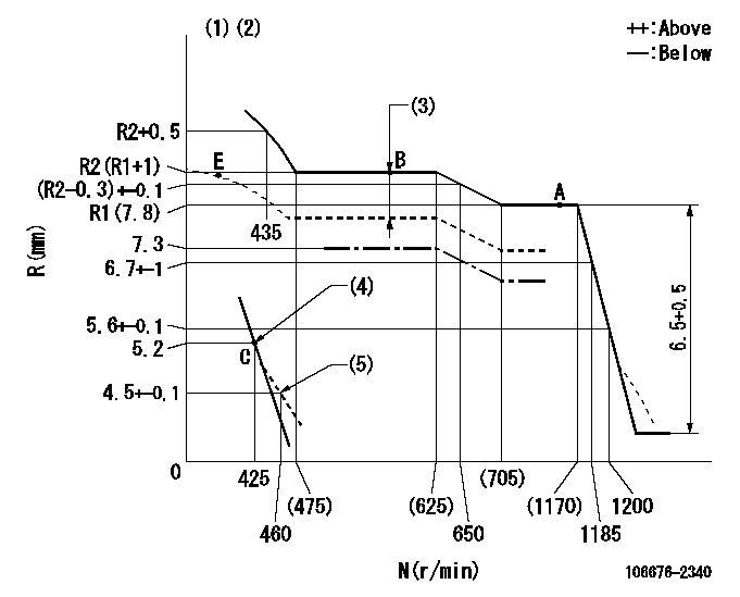
N:Pump speed
R:Rack position (mm)
(1)Boost compensator cancel stroke: BSL
(2)Tolerance for racks not indicated: +-0.05mm.
(3)Boost compensator stroke: BCL
(4)Main spring setting
(5)Damper spring setting
----------
BSL=1.6mm BCL=0.5+-0.1mm
----------
----------
BSL=1.6mm BCL=0.5+-0.1mm
----------
Speed control lever angle
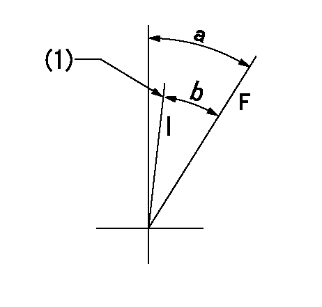
F:Full speed
I:Idle
(1)Stopper bolt setting
----------
----------
a=19deg+-5deg b=16.5deg+-5deg
----------
----------
a=19deg+-5deg b=16.5deg+-5deg
0000000901
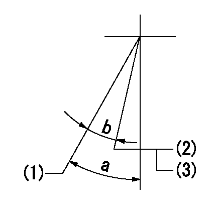
(1)Normal full load
(2)Rack position = aa, speed = bb (half load)
(3)Stopper bolt setting
----------
aa=7.3mm bb=550r/min
----------
a=25deg+-5deg b=5.5deg+-3deg
----------
aa=7.3mm bb=550r/min
----------
a=25deg+-5deg b=5.5deg+-3deg
Stop lever angle
N:Pump normal
S:Stop the pump.
(1)Rack position = aa
(2)Stopper bolt setting
(3)Rack position = bb or less
(4)Stopper bolt setting
(5)Normal stop
(6)Use the hole above R = cc
(7)Set the stopper bolt at the lever angle.
(8)-
----------
aa=(15.3)mm bb=3.2mm cc=37mm
----------
a=40deg+-5deg b=8deg+-5deg
----------
aa=(15.3)mm bb=3.2mm cc=37mm
----------
a=40deg+-5deg b=8deg+-5deg
Timing setting

(1)Pump vertical direction
(2)Coupling's key groove position at No 1 cylinder's beginning of injection
(3)B.T.D.C.: aa
(4)-
----------
aa=12deg
----------
a=(6deg)
----------
aa=12deg
----------
a=(6deg)
Information:
This Program must be administered either before or after failure.In either case the decision whether to apply the Program is made by the dealer. When reporting the repair, use "PS42405" as the Part Numberand "7755" as the Group Number. If administered before failure, use "56" as the Warranty Claim Description Code and "T" as the SIMS Description code.If administered after failure, use "96" as the Warranty Claim Description Code, and "Z" as the SIMS Description Code.
The information supplied in this service letter may not be valid after the termination date of this program.Do not perform the work outlined in this Service Letter after the termination date without first contacting your Caterpillar product analyst.
TERMINATION DATE
31May2009
PROBLEM
The 207-5248 Injector Rock Arms used in some C18 Marine Engine applications have been found to crack and break through the adjusting screw threads at the nose of the arm.
AFFECTED PRODUCT
Model Identification Number
C18 CKH00359, 426, 741, 744-745, 748-749, 1542-1543, 1594, 1641-1642, 1763-1764, 1805, 2053
PARTS NEEDED
Qty
Part Number Description
6 10R4704 ARM AS-UI ROCKER
ACTION REQUIRED
Refer to attached Rework Procedure.
SERVICE CLAIM ALLOWANCES
Product smu/age whichever comes first Caterpillar Dealer Suggested Customer Suggested
Parts % Labor Hrs% Parts % Labor Hrs% Parts % Labor Hrs%
0-2000 hrs,
0-24 mo 100.0% 100.0% 0.0% 0.0% 0.0% 0.0%
This is a 4.0-hour job
PARTS DISPOSITION
Handle the parts in accordance with your Warranty Bulletin on warranty parts handling.
Rework Procedure
For the following units listed remove (6) 207-5248 Injector Rocker Arms, and replace with (6) 10R4704 Injector Rocker Arms.
For proper Disassembly & Assembly instructions of the injector rocker arms please refer to the following Publications in SIS Web. (SENR9832 Testing & Adjusting - Finding Top Dead Center Position for No. 1 Piston), (SENR9832 Testing & Adjusting - Electronic Unit Injector Adjusting & Setting), and (SENR9832 Testing & Adjusting - Engine Valve Lash Inspect/Adjust).
Note: It is important that while installing the 10R4704 Injector Rocker Arms, that the engine is in the proper position (Top Dead Center and 180 degrees out) so the Injector Rocker Arms are properly adjusted and set. It is also important that during the installation of the Injector Rocker Arms that the Exhaust Valve, and Intake Valve lash settings be inspected and if needed reset to factory specifications.
Note: During the rework process please inspect the 6I-0901 Rocker Arm Shafts for any signs of misalignment of the stud mounting holes, wear, damage, fretting etc. If damage is found to the shaft or if fretting or damage is found with any of the through bolt/stud mounting holes, the shaft is to be replaced, and reported against this service letter as contingent damage.
Have questions with 106676-2340?
Group cross 106676-2340 ZEXEL
106676-2340
INJECTION-PUMP ASSEMBLY