Information injection-pump assembly
ZEXEL
106676-2333
1066762333
MITSUBISHI
ME444310
me444310
Rating:
Service parts 106676-2333 INJECTION-PUMP ASSEMBLY:
1.
_
7.
COUPLING PLATE
8.
_
9.
_
11.
Nozzle and Holder
12.
Open Pre:MPa(Kqf/cm2)
17.7(180)/21.6(220)
15.
NOZZLE SET
Include in #1:
106676-2333
as INJECTION-PUMP ASSEMBLY
Cross reference number
ZEXEL
106676-2333
1066762333
MITSUBISHI
ME444310
me444310
Zexel num
Bosch num
Firm num
Name
Calibration Data:
Adjustment conditions
Test oil
1404 Test oil ISO4113 or {SAEJ967d}
1404 Test oil ISO4113 or {SAEJ967d}
Test oil temperature
degC
40
40
45
Nozzle and nozzle holder
105780-8140
Bosch type code
EF8511/9A
Nozzle
105780-0000
Bosch type code
DN12SD12T
Nozzle holder
105780-2080
Bosch type code
EF8511/9
Opening pressure
MPa
17.2
Opening pressure
kgf/cm2
175
Injection pipe
Outer diameter - inner diameter - length (mm) mm 8-3-600
Outer diameter - inner diameter - length (mm) mm 8-3-600
Overflow valve
131424-4620
Overflow valve opening pressure
kPa
255
221
289
Overflow valve opening pressure
kgf/cm2
2.6
2.25
2.95
Tester oil delivery pressure
kPa
157
157
157
Tester oil delivery pressure
kgf/cm2
1.6
1.6
1.6
Direction of rotation (viewed from drive side)
Right R
Right R
Injection timing adjustment
Direction of rotation (viewed from drive side)
Right R
Right R
Injection order
1-5-3-6-
2-4
Pre-stroke
mm
4.8
4.75
4.85
Beginning of injection position
Governor side NO.1
Governor side NO.1
Difference between angles 1
Cal 1-5 deg. 60 59.5 60.5
Cal 1-5 deg. 60 59.5 60.5
Difference between angles 2
Cal 1-3 deg. 120 119.5 120.5
Cal 1-3 deg. 120 119.5 120.5
Difference between angles 3
Cal 1-6 deg. 180 179.5 180.5
Cal 1-6 deg. 180 179.5 180.5
Difference between angles 4
Cyl.1-2 deg. 240 239.5 240.5
Cyl.1-2 deg. 240 239.5 240.5
Difference between angles 5
Cal 1-4 deg. 300 299.5 300.5
Cal 1-4 deg. 300 299.5 300.5
Injection quantity adjustment
Adjusting point
-
Rack position
8.4
Pump speed
r/min
1000
1000
1000
Each cylinder's injection qty
mm3/st.
101.5
98.5
104.5
Basic
*
Fixing the rack
*
Standard for adjustment of the maximum variation between cylinders
*
Injection quantity adjustment_02
Adjusting point
C
Rack position
5.5+-0.5
Pump speed
r/min
350
350
350
Each cylinder's injection qty
mm3/st.
12
10.2
13.8
Fixing the rack
*
Standard for adjustment of the maximum variation between cylinders
*
Injection quantity adjustment_03
Adjusting point
A
Rack position
R1(8.4)
Pump speed
r/min
1000
1000
1000
Average injection quantity
mm3/st.
101.5
99.5
103.5
Basic
*
Fixing the lever
*
Injection quantity adjustment_04
Adjusting point
B
Rack position
R1+0.85
Pump speed
r/min
700
700
700
Average injection quantity
mm3/st.
116
110
122
Fixing the lever
*
Injection quantity adjustment_05
Adjusting point
D
Rack position
R2(R1+1)
Pump speed
r/min
500
500
500
Average injection quantity
mm3/st.
117.5
109.9
125.1
Fixing the lever
*
Injection quantity adjustment_06
Adjusting point
E
Rack position
10.6+-0.
5
Pump speed
r/min
100
100
100
Average injection quantity
mm3/st.
100
60
140
Fixing the lever
*
Boost compensator adjustment
Pump speed
r/min
500
500
500
Rack position
R2(R1+1)
Boost pressure
kPa
7.3
6
8.6
Boost pressure
mmHg
55
45
65
Boost compensator adjustment_02
Pump speed
r/min
500
500
500
Rack position
(10)
Boost pressure
kPa
13.3
13.3
13.3
Boost pressure
mmHg
100
100
100
Timer adjustment
Pump speed
r/min
0
Advance angle
deg.
2.5
2
3
Timer adjustment_02
Pump speed
r/min
N1
Advance angle
deg.
2.5
2
3
Remarks
Measure speed (beginning of operation).
Measure speed (beginning of operation).
Timer adjustment_03
Pump speed
r/min
-
Advance angle
deg.
0
0
0
Remarks
Measure the actual speed, stop
Measure the actual speed, stop
Test data Ex:
Governor adjustment
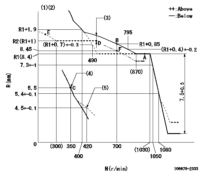
N:Pump speed
R:Rack position (mm)
(1)Boost compensator cancel stroke: BSL
(2)Tolerance for racks not indicated: +-0.05mm.
(3)Boost compensator stroke: BCL
(4)Main spring setting
(5)Damper spring setting
----------
BSL=1.6mm BCL=(0.6)mm
----------
----------
BSL=1.6mm BCL=(0.6)mm
----------
Speed control lever angle

F:Full speed
I:Idle
(1)Stopper bolt setting
----------
----------
a=15.5deg+-5deg b=15deg+-5deg
----------
----------
a=15.5deg+-5deg b=15deg+-5deg
0000000901
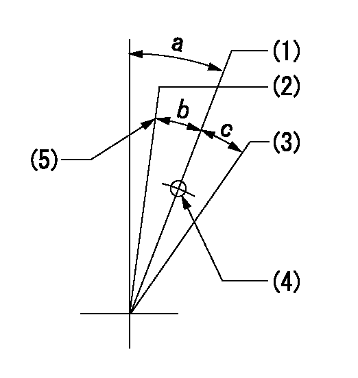
(1)Normal full load
(2)Rack position = aa, speed = bb (half load)
(3)Lever cancel angle
(4)Use the hole above R = cc
(5)Stopper bolt setting
----------
aa=8.45mm bb=700r/min cc=75mm
----------
a=10deg+-5deg b=3deg+-3deg c=(11.5deg)
----------
aa=8.45mm bb=700r/min cc=75mm
----------
a=10deg+-5deg b=3deg+-3deg c=(11.5deg)
Stop lever angle
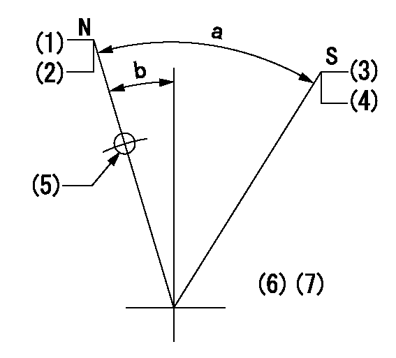
N:Pump normal
S:Stop the pump.
(1)Rack position = aa
(2)Stopper bolt setting
(3)Rack position = bb or less
(4)Stopper bolt setting
(5)Use the hole above R = cc
(6)No return spring
(7)Set the stopper bolt at the lever angle.
----------
aa=(15.3)mm bb=3.2mm cc=37mm
----------
a=40deg+-5deg b=8deg+-5deg
----------
aa=(15.3)mm bb=3.2mm cc=37mm
----------
a=40deg+-5deg b=8deg+-5deg
Timing setting

(1)Pump vertical direction
(2)Coupling's key groove position at No 1 cylinder's beginning of injection
(3)B.T.D.C.: aa
(4)-
----------
aa=12deg
----------
a=(6deg)
----------
aa=12deg
----------
a=(6deg)
Information:
22Mar2007
B99R
D99L
E99U
H74D
N73R
P70C
Z237
Z377
Before/After
(Limited distribution)
PRODUCT SUPPORT PROGRAM FOR REWORKING INJECTOR HEIGHT SETTINGS ON CERTAIN 2007 C13 ENGINES.
1290 PS42366
This Program must be administered either before or after failure.In either case the decision whether to apply the Program is made by the dealer. When reporting the repair, use "PS42366" as the Part Numberand "7755" as the Group Number. If administered before failure, use "56" as the Warranty Claim Description Code and "T" as the SIMS Description code.If administered after failure, use "96" as the Warranty Claim Description Code, and "Z" as the SIMS Description Code.
The information supplied in this service letter may not be valid after the termination date of this program.Do not perform the work outlined in this Service Letter after the termination date without first contacting your Caterpillar product analyst.
TERMINATION DATE
31Mar2009
PROBLEM
The existing injector height can be misadjusted on certain 2007 C13 Engines. If the injector height is set incorrectly it can/will cause an engine misfire.
AFFECTED PRODUCT
Model Identification Number
C13 LEE01022-01025, 1028, 1034, 1036, 1039, 1042, 1045, 1048-1052, 1055-1056, 1058, 1062, 1070-1071, 1073, 1079-1081, 1083, 1096, 1099-1100, 1103, 1117, 1119, 1127-1128, 1185-1186, 1188-1192, 1198, 1202, 1211-1212, 1219-1220
PARTS NEEDED
No parts needed for this program
ACTION REQUIRED
Perform Electronic Unit Injector-Adjust on all six injectors listed under Testing and Adjusting in Media Number RENR9808-04.
SERVICE CLAIM ALLOWANCES
Product smu/age whichever comes first Caterpillar Dealer Suggested Customer Suggested
Parts % Labor Hrs% Parts % Labor Hrs% Parts % Labor Hrs%
0-150000 miles,
0-12 mo 100.0% 100.0% 0.0% 0.0% 0.0% 0.0%
This is a 2.2-hour job
PARTS DISPOSITION
Handle the parts in accordance with your Warranty Bulletin on warranty parts handling.