Information injection-pump assembly
BOSCH
9 400 617 440
9400617440
ZEXEL
106676-2332
1066762332
MITSUBISHI
ME158828
me158828
Rating:
Service parts 106676-2332 INJECTION-PUMP ASSEMBLY:
1.
_
7.
COUPLING PLATE
8.
_
9.
_
11.
Nozzle and Holder
12.
Open Pre:MPa(Kqf/cm2)
17.7(180)/21.6(220)
15.
NOZZLE SET
Include in #1:
106676-2332
as INJECTION-PUMP ASSEMBLY
Cross reference number
BOSCH
9 400 617 440
9400617440
ZEXEL
106676-2332
1066762332
MITSUBISHI
ME158828
me158828
Zexel num
Bosch num
Firm num
Name
9 400 617 440
ME158828 MITSUBISHI
INJECTION-PUMP ASSEMBLY
6D24-T * K 14CA INJECTION PUMP ASSY PE6P,6PD PE
6D24-T * K 14CA INJECTION PUMP ASSY PE6P,6PD PE
Calibration Data:
Adjustment conditions
Test oil
1404 Test oil ISO4113 or {SAEJ967d}
1404 Test oil ISO4113 or {SAEJ967d}
Test oil temperature
degC
40
40
45
Nozzle and nozzle holder
105780-8140
Bosch type code
EF8511/9A
Nozzle
105780-0000
Bosch type code
DN12SD12T
Nozzle holder
105780-2080
Bosch type code
EF8511/9
Opening pressure
MPa
17.2
Opening pressure
kgf/cm2
175
Injection pipe
Outer diameter - inner diameter - length (mm) mm 8-3-600
Outer diameter - inner diameter - length (mm) mm 8-3-600
Overflow valve
131424-4620
Overflow valve opening pressure
kPa
255
255
255
Overflow valve opening pressure
kgf/cm2
2.6
2.6
2.6
Tester oil delivery pressure
kPa
157
157
157
Tester oil delivery pressure
kgf/cm2
1.6
1.6
1.6
Direction of rotation (viewed from drive side)
Right R
Right R
Injection timing adjustment
Direction of rotation (viewed from drive side)
Right R
Right R
Injection order
1-5-3-6-
2-4
Pre-stroke
mm
4.8
4.75
4.85
Beginning of injection position
Governor side NO.1
Governor side NO.1
Difference between angles 1
Cal 1-5 deg. 60 59.5 60.5
Cal 1-5 deg. 60 59.5 60.5
Difference between angles 2
Cal 1-3 deg. 120 119.5 120.5
Cal 1-3 deg. 120 119.5 120.5
Difference between angles 3
Cal 1-6 deg. 180 179.5 180.5
Cal 1-6 deg. 180 179.5 180.5
Difference between angles 4
Cyl.1-2 deg. 240 239.5 240.5
Cyl.1-2 deg. 240 239.5 240.5
Difference between angles 5
Cal 1-4 deg. 300 299.5 300.5
Cal 1-4 deg. 300 299.5 300.5
Injection quantity adjustment
Adjusting point
-
Rack position
8.4
Pump speed
r/min
1000
1000
1000
Each cylinder's injection qty
mm3/st.
101.5
98.5
104.5
Basic
*
Fixing the rack
*
Standard for adjustment of the maximum variation between cylinders
*
Injection quantity adjustment_02
Adjusting point
C
Rack position
5.5+-0.5
Pump speed
r/min
350
350
350
Each cylinder's injection qty
mm3/st.
12
10.2
13.8
Fixing the rack
*
Standard for adjustment of the maximum variation between cylinders
*
Injection quantity adjustment_03
Adjusting point
A
Rack position
R1(8.4)
Pump speed
r/min
1000
1000
1000
Average injection quantity
mm3/st.
101.5
99.5
103.5
Basic
*
Fixing the lever
*
Boost pressure
kPa
26.7
26.7
Boost pressure
mmHg
200
200
Injection quantity adjustment_04
Adjusting point
B
Rack position
R1+0.85
Pump speed
r/min
700
700
700
Average injection quantity
mm3/st.
116
110
122
Fixing the lever
*
Boost pressure
kPa
26.7
26.7
Boost pressure
mmHg
200
200
Injection quantity adjustment_05
Adjusting point
D
Rack position
R2[R1+1]
Pump speed
r/min
500
500
500
Average injection quantity
mm3/st.
117.5
109.9
125.1
Fixing the lever
*
Boost pressure
kPa
0
0
0
Boost pressure
mmHg
0
0
0
Injection quantity adjustment_06
Adjusting point
E
Rack position
-
Pump speed
r/min
100
100
100
Average injection quantity
mm3/st.
100
60
140
Fixing the lever
*
Boost pressure
kPa
0
0
0
Boost pressure
mmHg
0
0
0
Boost compensator adjustment
Pump speed
r/min
500
500
500
Rack position
R2[R1+1]
Boost pressure
kPa
7.3
6
8.6
Boost pressure
mmHg
55
45
65
Boost compensator adjustment_02
Pump speed
r/min
500
500
500
Rack position
(10)
Boost pressure
kPa
13.3
13.3
13.3
Boost pressure
mmHg
100
100
100
Timer adjustment
Pump speed
r/min
0
Advance angle
deg.
2.5
2
3
Timer adjustment_02
Pump speed
r/min
N1
Advance angle
deg.
2.5
2
3
Remarks
Measure speed (beginning of operation).
Measure speed (beginning of operation).
Timer adjustment_03
Pump speed
r/min
-
Advance angle
deg.
0
0
0
Remarks
Measure the actual speed, stop
Measure the actual speed, stop
Test data Ex:
Governor adjustment
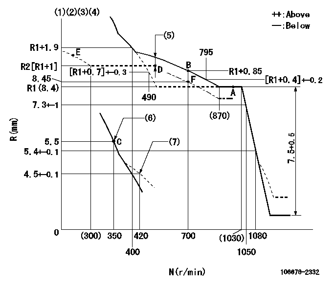
N:Pump speed
R:Rack position (mm)
(1)Lever ratio: RT
(2)Target shim dimension: TH
(3)Boost compensator cancel stroke: BSL
(4)Tolerance for racks not indicated: +-0.05mm.
(5)Boost compensator stroke: BCL
(6)Main spring setting
(7)Damper spring setting
----------
RT=1 TH=1.9mm BSL=1.6mm BCL=(0.6)mm
----------
----------
RT=1 TH=1.9mm BSL=1.6mm BCL=(0.6)mm
----------
Speed control lever angle

F:Full speed
I:Idle
(1)Stopper bolt setting
----------
----------
a=15.5deg+-5deg b=15deg+-5deg
----------
----------
a=15.5deg+-5deg b=15deg+-5deg
0000000901
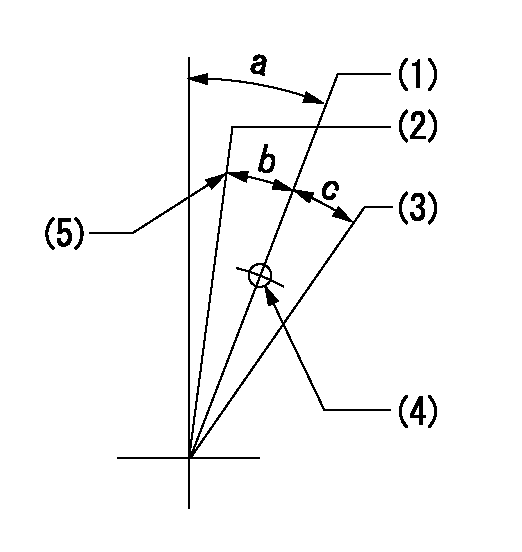
(1)Normal full load
(2)Rack position = aa, speed = bb (half load)
(3)Lever cancel angle
(4)Use the hole above R = cc
(5)Stopper bolt setting
----------
aa=8.45mm bb=700r/min cc=75mm
----------
a=10deg+-5deg b=3deg+-3deg c=(11.5deg)
----------
aa=8.45mm bb=700r/min cc=75mm
----------
a=10deg+-5deg b=3deg+-3deg c=(11.5deg)
Stop lever angle
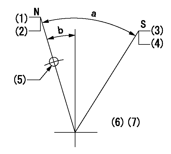
N:Pump normal
S:Stop the pump.
(1)Rack position = aa
(2)Stopper bolt setting
(3)Rack position = bb or less
(4)Stopper bolt setting
(5)Use the hole above R = cc
(6)No return spring
(7)Set the stopper bolt at the lever angle.
----------
aa=(15.3)mm bb=3.2mm cc=37mm
----------
a=40deg+-5deg b=8deg+-5deg
----------
aa=(15.3)mm bb=3.2mm cc=37mm
----------
a=40deg+-5deg b=8deg+-5deg
Timing setting

(1)Pump vertical direction
(2)Coupling's key groove position at No 1 cylinder's beginning of injection
(3)B.T.D.C.: aa
(4)-
----------
aa=12deg
----------
a=(6deg)
----------
aa=12deg
----------
a=(6deg)
Information:
Image1.1.1
5. Attach a hose to the other end of the fuel rail and hold the free end of the hose in a cup/bucket of water. Hose shown is a JIC 37o ?6 hose. Refer to Illustration 1.2.1
Image1.2.1
6. Pressurize the cooling system with compressed air and regulate pressure between 5-15 psi.
Do Not Exceed 15 psi or Cooling System Damage Can Result.
7. Submerse the hose in a cup/bucket of water.
8. Monitor for 10 minutes and check for a steady rate of air bubbles coming out of the hose that is submersed in the cup/bucket of water.
9. If steady stream of air is present, replace the cylinder head, coolant regulators, and both 030-7937 port connectors. Depending on the application, you will need to replace some cooling system seals. (List of seals by application to be included)
10. Once the cylinder heads have been replaced pressure test the head again using the same procedure. Once this has been completed the cooling system should be flushed using instructions listed below.
Cleaning the Cooling System
1. Drain all of the coolant form cooling system.
2. Fill the cooling system with clean water.
3. Start engine and run it until the thermostat opens.
4. Add two cups of non-foaming liquid automatic dish washer soap.
Note: Do not use plain dish soap. Aeration of the cooling system and resultant damage could occur.
5. After the soap has bee added run engine for approximately twenty minutes. Check to see if the fuel is breaking up.
6. If the fuel is still not breaking up than add two more cups of soap and run for 10 minutes. Drain mixture from cooling system.
7. Fill cooling system with clean water and check surface for fuel. If fuel is present, repeat steps 3 through 7. When water is clear, drain and rinse the cooling system one more time. Then add coolant and conditioner.