Information injection-pump assembly
ZEXEL
106676-2330
1066762330

Rating:
Cross reference number
ZEXEL
106676-2330
1066762330
Zexel num
Bosch num
Firm num
Name
106676-2330
INJECTION-PUMP ASSEMBLY
Calibration Data:
Adjustment conditions
Test oil
1404 Test oil ISO4113 or {SAEJ967d}
1404 Test oil ISO4113 or {SAEJ967d}
Test oil temperature
degC
40
40
45
Nozzle and nozzle holder
105780-8140
Bosch type code
EF8511/9A
Nozzle
105780-0000
Bosch type code
DN12SD12T
Nozzle holder
105780-2080
Bosch type code
EF8511/9
Opening pressure
MPa
17.2
Opening pressure
kgf/cm2
175
Injection pipe
Outer diameter - inner diameter - length (mm) mm 8-3-600
Outer diameter - inner diameter - length (mm) mm 8-3-600
Overflow valve
131424-4620
Overflow valve opening pressure
kPa
255
221
289
Overflow valve opening pressure
kgf/cm2
2.6
2.25
2.95
Tester oil delivery pressure
kPa
157
157
157
Tester oil delivery pressure
kgf/cm2
1.6
1.6
1.6
Direction of rotation (viewed from drive side)
Right R
Right R
Injection timing adjustment
Direction of rotation (viewed from drive side)
Right R
Right R
Injection order
1-5-3-6-
2-4
Pre-stroke
mm
4.8
4.75
4.85
Beginning of injection position
Governor side NO.1
Governor side NO.1
Difference between angles 1
Cal 1-5 deg. 60 59.5 60.5
Cal 1-5 deg. 60 59.5 60.5
Difference between angles 2
Cal 1-3 deg. 120 119.5 120.5
Cal 1-3 deg. 120 119.5 120.5
Difference between angles 3
Cal 1-6 deg. 180 179.5 180.5
Cal 1-6 deg. 180 179.5 180.5
Difference between angles 4
Cyl.1-2 deg. 240 239.5 240.5
Cyl.1-2 deg. 240 239.5 240.5
Difference between angles 5
Cal 1-4 deg. 300 299.5 300.5
Cal 1-4 deg. 300 299.5 300.5
Injection quantity adjustment
Adjusting point
-
Rack position
8.5
Pump speed
r/min
1000
1000
1000
Each cylinder's injection qty
mm3/st.
104.5
101.4
107.6
Basic
*
Fixing the rack
*
Standard for adjustment of the maximum variation between cylinders
*
Injection quantity adjustment_02
Adjusting point
C
Rack position
5.2+-0.5
Pump speed
r/min
425
425
425
Each cylinder's injection qty
mm3/st.
9
7.6
10.4
Fixing the rack
*
Standard for adjustment of the maximum variation between cylinders
*
Injection quantity adjustment_03
Adjusting point
A
Rack position
R1(8.5)
Pump speed
r/min
1000
1000
1000
Average injection quantity
mm3/st.
104.5
102.5
106.5
Basic
*
Fixing the lever
*
Boost pressure
kPa
22
22
Boost pressure
mmHg
165
165
Injection quantity adjustment_04
Adjusting point
B
Rack position
R2(R1+1)
Pump speed
r/min
500
500
500
Average injection quantity
mm3/st.
121
115
127
Fixing the lever
*
Boost pressure
kPa
22
22
Boost pressure
mmHg
165
165
Injection quantity adjustment_05
Adjusting point
E
Rack position
-
Pump speed
r/min
100
100
100
Average injection quantity
mm3/st.
105
65
145
Fixing the lever
*
Boost pressure
kPa
0
0
0
Boost pressure
mmHg
0
0
0
Boost compensator adjustment
Pump speed
r/min
500
500
500
Rack position
R2-0.5
Boost pressure
kPa
3.3
3.3
5.3
Boost pressure
mmHg
25
25
40
Boost compensator adjustment_02
Pump speed
r/min
500
500
500
Rack position
R2(R1+1)
Boost pressure
kPa
11.3
7.3
15.3
Boost pressure
mmHg
85
55
115
Timer adjustment
Pump speed
r/min
0
Advance angle
deg.
2.5
2
3
Timer adjustment_02
Pump speed
r/min
-
Advance angle
deg.
2.5
2
3
Remarks
Measure speed (beginning of operation).
Measure speed (beginning of operation).
Timer adjustment_03
Pump speed
r/min
-
Advance angle
deg.
0
0
0
Remarks
Measure the actual speed, stop
Measure the actual speed, stop
Test data Ex:
Governor adjustment
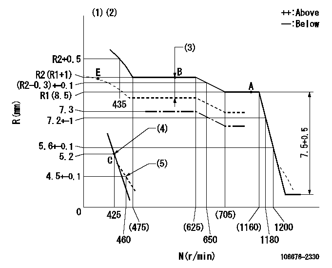
N:Pump speed
R:Rack position (mm)
(1)Boost compensator cancel stroke: BSL
(2)Tolerance for racks not indicated: +-0.05mm.
(3)Boost compensator stroke: BCL
(4)Main spring setting
(5)Damper spring setting
----------
BSL=1.6mm BCL=0.5+-0.1mm
----------
----------
BSL=1.6mm BCL=0.5+-0.1mm
----------
Speed control lever angle
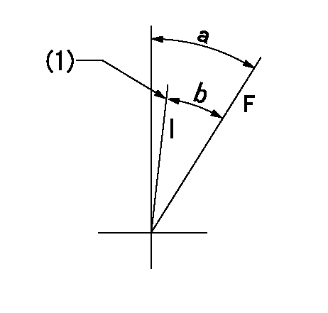
F:Full speed
I:Idle
(1)Stopper bolt setting
----------
----------
a=19deg+-5deg b=16.5deg+-5deg
----------
----------
a=19deg+-5deg b=16.5deg+-5deg
0000000901
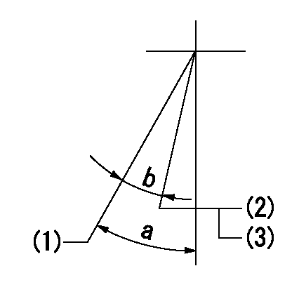
(1)Normal full load
(2)Rack position = aa, speed = bb (half load)
(3)Stopper bolt setting
----------
aa=7.3mm bb=550r/min
----------
a=25deg+-5deg b=8deg+-3deg
----------
aa=7.3mm bb=550r/min
----------
a=25deg+-5deg b=8deg+-3deg
Stop lever angle
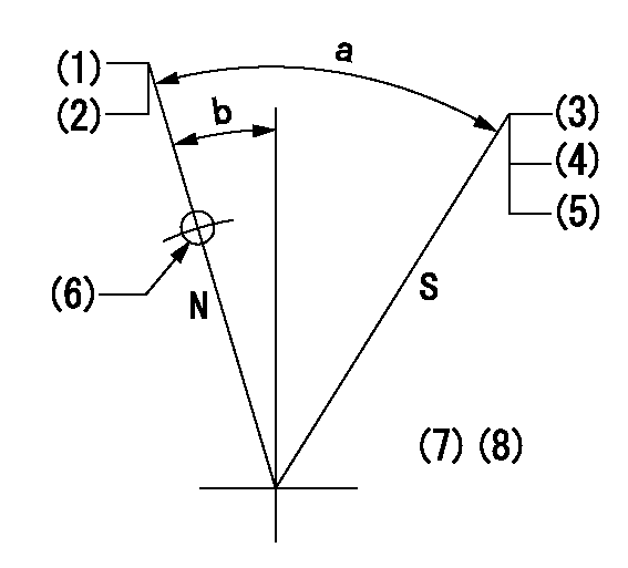
N:Pump normal
S:Stop the pump.
(1)Rack position = aa
(2)Stopper bolt setting
(3)Rack position = bb or less
(4)Stopper bolt setting
(5)Normal stop
(6)Use the hole above R = cc
(7)Set the stopper bolt at the lever angle.
(8)-
----------
aa=(15.3)mm bb=3.2mm cc=37mm
----------
a=40deg+-5deg b=8deg+-5deg
----------
aa=(15.3)mm bb=3.2mm cc=37mm
----------
a=40deg+-5deg b=8deg+-5deg
Timing setting

(1)Pump vertical direction
(2)Coupling's key groove position at No 1 cylinder's beginning of injection
(3)B.T.D.C.: aa
(4)-
----------
aa=12deg
----------
a=(6deg)
----------
aa=12deg
----------
a=(6deg)
Information:
The information supplied in this service letter may not be valid after the termination date of this program.Do not perform the work outlined in this Service Letter after the termination date without first contacting your Caterpillar product analyst.
COMPLETION DATE
TERMINATION DATE
28Feb2007 31Aug2007
PROBLEM
The torque on the 100-6920 Direct Injection Fuel Nozzle Adapters may be out of specification.
AFFECTED PRODUCT
Model Identification Number
3408C TAM00350-00351
3412 38S24043
BCS02130
3412C 9BR03238
9EP03871, 3969-3970, 3972-3973
DJN01044-01070, 1074-1076, 1081, 1087
RLR00339, 341-342
TFT00565-00583
PARTS NEEDED
No parts needed for this program
ACTION REQUIRED
Remove valve covers, fuel lines and fuel nozzles. Tighten the 100-6920 Direct Injection Fuel Nozzle Adapters to 200 +/- 14 Nm (150 +/- 10 lb ft). Reassemble engine. For detailed instructions, refer to the procedure in the Disassembly and Assembly manual. Test engine for proper operation after reassembly.
OWNER NOTIFICATION
U.S. and Canadian owners will receive the attached Owner Notification.
SERVICE CLAIM ALLOWANCES
Caterpillar Dealer Suggested Customer Suggested
Parts % Labor Hrs% Parts % Labor Hrs% Parts % Labor Hrs%
100% 100% 0% 0% 0% 0%
This is a 3.0-hour job
PARTS DISPOSITION
Handle the parts in accordance with your Warranty Bulletin on warranty parts handling.
MAKE EVERY EFFORT TO COMPLETE THIS PROGRAM AS SOON AS POSSIBLE.
COPY OF OWNER NOTIFICATION FOR U.S. AND CANADIAN OWNERS
XYZ Corporation
3240 Arrow Drive
Anywhere, YZ 99999
PRIORITY - PRODUCT IMPROVEMENT PROGRAM FOR TIGHTENING THE DIRECT INJECTION FUEL NOZZLE ADAPTERS
MODELS INVOLVED - Certain 3408 and 3412 Engines
Dear Caterpillar Product Owner:
The torque on the Direct Injection Fuel Nozzle Adapters may be out of specification. The Direct Injection Fuel Nozzle Adapters need to be tightened to the correct torque on the products listed below. You will not be charged for the service performed.
Contact your local Caterpillar dealer immediately to schedule this service. The dealer will advise you of the time required to complete this service.
Please refer the dealer to their Service Letter dated 24Aug2006 when scheduling this service.
We regret the inconvenience this may cause you, but urge you to have this service performed as soon as possible to prevent unscheduled downtime.
Caterpillar Inc.
Identification #(s)
Attached to 24Aug2006 Service Letter
Have questions with 106676-2330?
Group cross 106676-2330 ZEXEL
106676-2330
INJECTION-PUMP ASSEMBLY