Information injection-pump assembly
BOSCH
9 400 612 127
9400612127
ZEXEL
106676-2322
1066762322
MITSUBISHI
ME158824
me158824

Rating:
Service parts 106676-2322 INJECTION-PUMP ASSEMBLY:
1.
_
7.
COUPLING PLATE
8.
_
9.
_
11.
Nozzle and Holder
ME158263
12.
Open Pre:MPa(Kqf/cm2)
17.7{180}/21.6{220}
14.
NOZZLE
Include in #1:
106676-2322
as INJECTION-PUMP ASSEMBLY
Cross reference number
BOSCH
9 400 612 127
9400612127
ZEXEL
106676-2322
1066762322
MITSUBISHI
ME158824
me158824
Zexel num
Bosch num
Firm num
Name
106676-2322
9 400 612 127
ME158824 MITSUBISHI
INJECTION-PUMP ASSEMBLY
6D24T K 14CA INJECTION PUMP ASSY PE6P,6PD PE
6D24T K 14CA INJECTION PUMP ASSY PE6P,6PD PE
Calibration Data:
Adjustment conditions
Test oil
1404 Test oil ISO4113 or {SAEJ967d}
1404 Test oil ISO4113 or {SAEJ967d}
Test oil temperature
degC
40
40
45
Nozzle and nozzle holder
105780-8140
Bosch type code
EF8511/9A
Nozzle
105780-0000
Bosch type code
DN12SD12T
Nozzle holder
105780-2080
Bosch type code
EF8511/9
Opening pressure
MPa
17.2
Opening pressure
kgf/cm2
175
Injection pipe
Outer diameter - inner diameter - length (mm) mm 8-3-600
Outer diameter - inner diameter - length (mm) mm 8-3-600
Overflow valve
131424-4620
Overflow valve opening pressure
kPa
255
221
289
Overflow valve opening pressure
kgf/cm2
2.6
2.25
2.95
Tester oil delivery pressure
kPa
157
157
157
Tester oil delivery pressure
kgf/cm2
1.6
1.6
1.6
Direction of rotation (viewed from drive side)
Right R
Right R
Injection timing adjustment
Direction of rotation (viewed from drive side)
Right R
Right R
Injection order
1-5-3-6-
2-4
Pre-stroke
mm
4.8
4.75
4.85
Beginning of injection position
Governor side NO.1
Governor side NO.1
Difference between angles 1
Cal 1-5 deg. 60 59.5 60.5
Cal 1-5 deg. 60 59.5 60.5
Difference between angles 2
Cal 1-3 deg. 120 119.5 120.5
Cal 1-3 deg. 120 119.5 120.5
Difference between angles 3
Cal 1-6 deg. 180 179.5 180.5
Cal 1-6 deg. 180 179.5 180.5
Difference between angles 4
Cyl.1-2 deg. 240 239.5 240.5
Cyl.1-2 deg. 240 239.5 240.5
Difference between angles 5
Cal 1-4 deg. 300 299.5 300.5
Cal 1-4 deg. 300 299.5 300.5
Injection quantity adjustment
Adjusting point
A
Rack position
8.9
Pump speed
r/min
1000
1000
1000
Average injection quantity
mm3/st.
123
120
126
Max. variation between cylinders
%
0
-3
3
Basic
*
Fixing the lever
*
Boost pressure
kPa
30.7
30.7
Boost pressure
mmHg
230
230
Injection quantity adjustment_02
Adjusting point
B
Rack position
4.4+-0.5
Pump speed
r/min
425
425
425
Average injection quantity
mm3/st.
9.5
6.9
12.1
Max. variation between cylinders
%
0
-15
15
Fixing the rack
*
Boost pressure
kPa
0
0
0
Boost pressure
mmHg
0
0
0
Injection quantity adjustment_03
Adjusting point
D
Rack position
-
Pump speed
r/min
100
100
100
Average injection quantity
mm3/st.
145
125
165
Fixing the lever
*
Boost pressure
kPa
0
0
0
Boost pressure
mmHg
0
0
0
Rack limit
*
Boost compensator adjustment
Pump speed
r/min
700
700
700
Rack position
R1-1.25
Boost pressure
kPa
4
2.7
5.3
Boost pressure
mmHg
30
20
40
Boost compensator adjustment_02
Pump speed
r/min
700
700
700
Rack position
R1(8.9)
Boost pressure
kPa
17.3
10.6
24
Boost pressure
mmHg
130
80
180
Timer adjustment
Pump speed
r/min
0
Advance angle
deg.
2.5
2
3
Timer adjustment_02
Pump speed
r/min
300
Advance angle
deg.
2.5
2
3
Remarks
Start
Start
Timer adjustment_03
Pump speed
r/min
-
Advance angle
deg.
0
0
0
Remarks
Measure the actual speed, stop
Measure the actual speed, stop
Test data Ex:
Governor adjustment
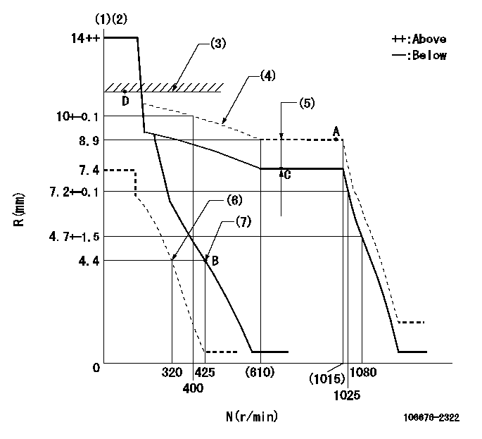
N:Pump speed
R:Rack position (mm)
(1)Notch fixed: K
(2)Tolerance for racks not indicated: +-0.05mm.
(3)RACK LIMIT
(4)The torque control spring must does not have a set force.
(5)Boost compensator stroke: BCL
(6)Set idle sub-spring
(7)Main spring setting
----------
K=8 BCL=1.25+-0.1mm
----------
----------
K=8 BCL=1.25+-0.1mm
----------
Speed control lever angle

F:Full speed
I:Idle
(1)Stopper bolt setting
----------
----------
a=(20deg)+-5deg b=(2deg)+-5deg
----------
----------
a=(20deg)+-5deg b=(2deg)+-5deg
Stop lever angle
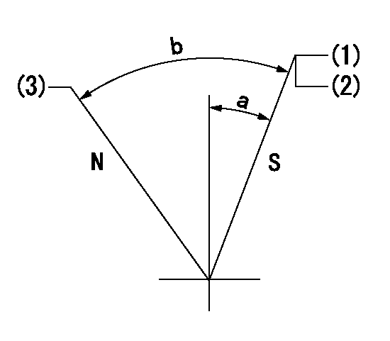
N:Pump normal
S:Stop the pump.
(1)Pump speed aa and rack position bb (to be sealed at delivery)
(2)Stopper bolt setting
(3)Normal
----------
aa=0r/min bb=1-0.5mm
----------
a=35deg+-5deg b=70deg+-5deg
----------
aa=0r/min bb=1-0.5mm
----------
a=35deg+-5deg b=70deg+-5deg
0000001501 TAMPER PROOF

Tamperproofing-equipped boost compensator cover installation procedure
(A) After adjusting the boost compensator, tighten the bolts to remove the heads.
(1)Before adjusting the governor and the boost compensator, tighten the screw to the specified torque.
(Tightening torque T = T1 maximum)
(2)After adjusting the governor and the boost compensator, tighten to the specified torque to break off the bolt heads.
(Tightening torque T = T2)
----------
T1=2.5N-m(0.25kgf-m) T2=2.9~4.4N-m(0.3~0.45kgf-m)
----------
----------
T1=2.5N-m(0.25kgf-m) T2=2.9~4.4N-m(0.3~0.45kgf-m)
----------
Timing setting

(1)Pump vertical direction
(2)Coupling's key groove position at No 1 cylinder's beginning of injection
(3)B.T.D.C.: aa
(4)-
----------
aa=12deg
----------
a=(6deg)
----------
aa=12deg
----------
a=(6deg)
Information:
PARTS NEEDED
Qty
Part Number Description
2 1790133 FILM-AIR SHUTOFF
2 2898498 DAMPER AS
ACTION REQUIRED
Refer to the attached Rework Procedure.
OWNER NOTIFICATION
U.S. and Canadian owners will receive the attached Owner Notification.
SERVICE CLAIM ALLOWANCES
Caterpillar Dealer Suggested Customer Suggested
Parts % Labor Hrs% Parts % Labor Hrs% Parts % Labor Hrs%
100% 100% 0% 0% 0% 0%
This is a 1.0-hour job
PARTS DISPOSITION
Handle the parts in accordance with your Warranty Bulletin on warranty parts handling.
MAKE EVERY EFFORT TO COMPLETE THIS PROGRAM AS SOON AS POSSIBLE.
COPY OF OWNER NOTIFICATION FOR U.S. AND CANADIAN OWNERS
XYZ Corporation
3240 Arrow Drive
Anywhere, YZ 99999
PRIORITY - PRODUCT IMPROVEMENT PROGRAM FOR ADDING VIBRATION DAMPERS TO AIR SHUT OFFS
MODELS INVOLVED - CERTAIN 3500 DIESEL ENGINES
Dear Caterpillar Product Owner:
New vibration dampers need to be installed on the products listed. You will not be charged for the service performed. Contact your local Caterpillar dealer immediately to schedule this service. The dealer will advise you of the time required to complete this service.
It is VERY IMPORTANT that your Air Shut Offs be tested every 500 operating hours and the vibration dampers installed on the ASOs need to be inspected/serviced every 6000 operating hours. Please contact your Caterpillar Dealer for a copy of Caterpillar Special Instruction REHS3005, which details this procedure. A COPY OF THIS DOCUMENT SHOULD BE PLACED IN THE APPLICABLE Operating and Maintenance Manuals.
Please refer the dealer to their Service Letter dated 27Jul2006 when scheduling this service.
We regret the inconvenience this may cause you, but urge you to have this service performed as soon as possible to prevent unscheduled downtime.
Caterpillar Inc.
Identification #(s)
Attached to 27Jul2006 Service Letter
Rework Procedure
1. Remove existing plug from bottom of each Air Shut Off (ASO) housing, Image 1.1.1
Image1.1.1
2. Install new Vibration Damper P/N 289-8498 into the hole as shown in image 1.2.1, insuring that the threads are coated with Thread lock P/N 9S-3263 or 4C-4030 and torque the damper to 16 (+/- 2)Nm.
Image1.2.1
3. Install information labels over existing labels on the electrically actuated ASO solenoids as shown in image 1.3.1 or on hydraulically actuated ASO valve covers as shown in image 1.3.2.
Labels in languages other than English are available under the following Part Numbers:
-Arabic 297-2613
-French 297-2614
-German 297-2615
-Spanish 297-2616
-Portuguese 297-2617
-Russian 297-2618
Image1.3.1
Image1.3.2
Have questions with 106676-2322?
Group cross 106676-2322 ZEXEL
Mitsubishi
Mitsubishi
106676-2322
9 400 612 127
ME158824
INJECTION-PUMP ASSEMBLY
6D24T
6D24T