Information injection-pump assembly
BOSCH
9 400 611 200
9400611200
ZEXEL
106676-2300
1066762300
MITSUBISHI
ME158630
me158630

Rating:
Service parts 106676-2300 INJECTION-PUMP ASSEMBLY:
1.
_
7.
COUPLING PLATE
8.
_
9.
_
11.
Nozzle and Holder
ME056473
12.
Open Pre:MPa(Kqf/cm2)
17.7{180}/21.6{220}

15.
NOZZLE SET
Include in #1:
106676-2300
as INJECTION-PUMP ASSEMBLY
Cross reference number
BOSCH
9 400 611 200
9400611200
ZEXEL
106676-2300
1066762300
MITSUBISHI
ME158630
me158630
Zexel num
Bosch num
Firm num
Name
106676-2300
9 400 611 200
ME158630 MITSUBISHI
INJECTION-PUMP ASSEMBLY
6D24TC K 14CA INJECTION PUMP ASSY PE6P,6PD PE
6D24TC K 14CA INJECTION PUMP ASSY PE6P,6PD PE
Calibration Data:
Adjustment conditions
Test oil
1404 Test oil ISO4113 or {SAEJ967d}
1404 Test oil ISO4113 or {SAEJ967d}
Test oil temperature
degC
40
40
45
Nozzle and nozzle holder
105780-8140
Bosch type code
EF8511/9A
Nozzle
105780-0000
Bosch type code
DN12SD12T
Nozzle holder
105780-2080
Bosch type code
EF8511/9
Opening pressure
MPa
17.2
Opening pressure
kgf/cm2
175
Injection pipe
Outer diameter - inner diameter - length (mm) mm 8-3-600
Outer diameter - inner diameter - length (mm) mm 8-3-600
Overflow valve
131424-4620
Overflow valve opening pressure
kPa
255
221
289
Overflow valve opening pressure
kgf/cm2
2.6
2.25
2.95
Tester oil delivery pressure
kPa
157
157
157
Tester oil delivery pressure
kgf/cm2
1.6
1.6
1.6
Direction of rotation (viewed from drive side)
Right R
Right R
Injection timing adjustment
Direction of rotation (viewed from drive side)
Right R
Right R
Injection order
1-5-3-6-
2-4
Pre-stroke
mm
4.8
4.75
4.85
Beginning of injection position
Governor side NO.1
Governor side NO.1
Difference between angles 1
Cal 1-5 deg. 60 59.5 60.5
Cal 1-5 deg. 60 59.5 60.5
Difference between angles 2
Cal 1-3 deg. 120 119.5 120.5
Cal 1-3 deg. 120 119.5 120.5
Difference between angles 3
Cal 1-6 deg. 180 179.5 180.5
Cal 1-6 deg. 180 179.5 180.5
Difference between angles 4
Cyl.1-2 deg. 240 239.5 240.5
Cyl.1-2 deg. 240 239.5 240.5
Difference between angles 5
Cal 1-4 deg. 300 299.5 300.5
Cal 1-4 deg. 300 299.5 300.5
Injection quantity adjustment
Adjusting point
A
Rack position
10.6
Pump speed
r/min
1000
1000
1000
Average injection quantity
mm3/st.
168.5
165.5
171.5
Max. variation between cylinders
%
0
-3
3
Basic
*
Fixing the lever
*
Boost pressure
kPa
36
36
Boost pressure
mmHg
270
270
Injection quantity adjustment_02
Adjusting point
B
Rack position
6+-0.5
Pump speed
r/min
425
425
425
Average injection quantity
mm3/st.
8
5.4
10.6
Max. variation between cylinders
%
0
-15
15
Fixing the rack
*
Boost pressure
kPa
0
0
0
Boost pressure
mmHg
0
0
0
Injection quantity adjustment_03
Adjusting point
D
Rack position
-
Pump speed
r/min
100
100
100
Average injection quantity
mm3/st.
195
175
215
Fixing the lever
*
Boost pressure
kPa
0
0
0
Boost pressure
mmHg
0
0
0
Rack limit
*
Boost compensator adjustment
Pump speed
r/min
600
600
600
Rack position
R1-1.65
Boost pressure
kPa
4
2.7
5.3
Boost pressure
mmHg
30
20
40
Boost compensator adjustment_02
Pump speed
r/min
600
600
600
Rack position
R1-0.25
Boost pressure
kPa
20
13.3
26.7
Boost pressure
mmHg
150
100
200
Boost compensator adjustment_03
Pump speed
r/min
600
600
600
Rack position
R1(10.6)
Boost pressure
kPa
22.7
22.7
22.7
Boost pressure
mmHg
170
170
170
Timer adjustment
Pump speed
r/min
825--
Advance angle
deg.
0
0
0
Remarks
Start
Start
Timer adjustment_02
Pump speed
r/min
775
Advance angle
deg.
0.5
Timer adjustment_03
Pump speed
r/min
975
Advance angle
deg.
1
0.5
1.5
Remarks
Finish
Finish
Test data Ex:
Governor adjustment
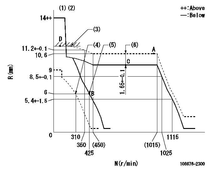
N:Pump speed
R:Rack position (mm)
(1)Notch fixed: K
(2)Tolerance for racks not indicated: +-0.05mm.
(3)RACK LIMIT
(4)Set idle sub-spring
(5)Main spring setting
(6)Boost compensator stroke
----------
K=11
----------
----------
K=11
----------
Speed control lever angle

F:Full speed
I:Idle
(1)Stopper bolt setting
----------
----------
a=(20deg)+-5deg b=(4deg)+-5deg
----------
----------
a=(20deg)+-5deg b=(4deg)+-5deg
Stop lever angle
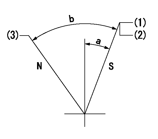
N:Pump normal
S:Stop the pump.
(1)Pump speed aa and rack position bb (to be sealed at delivery)
(2)Stopper bolt setting
(3)Normal
----------
aa=0r/min bb=1-0.5mm
----------
a=35deg+-5deg b=70deg+-5deg
----------
aa=0r/min bb=1-0.5mm
----------
a=35deg+-5deg b=70deg+-5deg
0000001501 TAMPER PROOF

Tamperproofing-equipped boost compensator cover installation procedure
(A) After adjusting the boost compensator, tighten the bolts to remove the heads.
(1)Before adjusting the governor and the boost compensator, tighten the screw to the specified torque.
(Tightening torque T = T1 maximum)
(2)After adjusting the governor and the boost compensator, tighten to the specified torque to break off the bolt heads.
(Tightening torque T = T2)
----------
T1=2.5N-m(0.25kgf-m) T2=2.9~4.4N-m(0.3~0.45kgf-m)
----------
----------
T1=2.5N-m(0.25kgf-m) T2=2.9~4.4N-m(0.3~0.45kgf-m)
----------
Timing setting

(1)Pump vertical direction
(2)Coupling's key groove position at No 1 cylinder's beginning of injection
(3)B.T.D.C.: aa
(4)-
----------
aa=13deg
----------
a=(7deg)
----------
aa=13deg
----------
a=(7deg)
Information:
AUGUST 2011
INFORMATION RELEASE MEMO
Reman
PELJ1306 ?2011 Caterpillar REMAN DIESEL PARTICULATE FILTERS FOR MACHINE APPLICATIONS
To provide our customers with cost effective service options to support their Tier 4 emissions engines, Cat Reman has released a Reman version of the diesel particulate filters (DPF) used on many Tier 4 Cat? machines. The DPF traps both soot and ash. Soot is removed through a regeneration process outlined in the machines operation and maintenance manual. Ash that accumulates from engine oil is removed through a cleaning procedure that requires removal of the DPF from the machine. The cleaning procedure requires the DPF to be removed from the machine. Special Instruction REHS5045 outlines the three approved processes for performing the required Diesel Particulate Filter (DPF) maintenance on Tier 4 products equipped with a DPF.
Replacement of the existing DPF with a new Cat DPF
Replacement of the existing DPF with a remanufactured Cat DPF
Removal of the existing DPF and having the DPF cleaned by a Cat approved cleaning device.
The Reman DPFs listed below are available to support these maintenance requirements:
Core Acceptance
After gaining some experience with the previously released DPFs used for on-highway engines and to support the launch of these additional machine DPFs, we have changed some of the inspection criteria and issued a revision to SELD0292. SELD0292-02 Caterpillar Diesel Particulate Filter (DPF) is the current Core Acceptance Criteria (CAC). It is critical to avoid non-operational damage that can decrease the value of the cores. Encourage service technicians to handle and package the cores with care so they will be more likely to be eligible for the full core refunds. Please always refer to the most current version at catreman.cat.com/core to view the latest requirements. The acceptability inspection for these is a simple visual inspection based on the following guidelines:
Warranty
All Reman products carry the same warranty as new parts. Please consult the appropriate warranty statement for your area.
Core Management
Please refer to the Cat Core Management Information System (CMIS 2) related to the parts information application that describes all Reman part/Core Acceptability Family (CAF) and other related information. Also refer to other CMIS 2 inquiry applications such as: Dealer Customer Profile, Inspection Reason Codes, Inspection Line Inquiry, Dealer Add Charges, Dealer Entitlement Activity, Dealer CCR Inquiry, Dealer CCR Entry, Dealer Shipment Processing, Dealer Process Packaging Grief and Reporting. This information is available to all dealers worldwide that have been converted to CMIS 2.
Please go to the Reman web site https://catreman.cat.com for the latest policy and procedural updates that are available to all dealers worldwide explaining policy and procedural information such as Policy and Core Management SELD0122 -10, "Core Management Systems and Operations Procedures SELD0040-14, "Reman Core Return Packaging Instructions And Guidelines SELD0300-00 and "Shipping Instructions" SELD0039-14.
If you have any questions regarding Reman Core Management or Core Management Systems (CMIS2),
Have questions with 106676-2300?
Group cross 106676-2300 ZEXEL
Mitsubishi
106676-2300
9 400 611 200
ME158630
INJECTION-PUMP ASSEMBLY
6D24TC
6D24TC