Information injection-pump assembly
BOSCH
9 400 617 427
9400617427
ZEXEL
106676-2071
1066762071
MITSUBISHI
ME158579
me158579
Rating:
Cross reference number
BOSCH
9 400 617 427
9400617427
ZEXEL
106676-2071
1066762071
MITSUBISHI
ME158579
me158579
Zexel num
Bosch num
Firm num
Name
106676-2071
9 400 617 427
ME158579 MITSUBISHI
INJECTION-PUMP ASSEMBLY
6D24T K 14CA INJECTION PUMP ASSY PE6P,6PD PE
6D24T K 14CA INJECTION PUMP ASSY PE6P,6PD PE
Calibration Data:
Adjustment conditions
Test oil
1404 Test oil ISO4113 or {SAEJ967d}
1404 Test oil ISO4113 or {SAEJ967d}
Test oil temperature
degC
40
40
45
Nozzle and nozzle holder
105780-8140
Bosch type code
EF8511/9A
Nozzle
105780-0000
Bosch type code
DN12SD12T
Nozzle holder
105780-2080
Bosch type code
EF8511/9
Opening pressure
MPa
17.2
Opening pressure
kgf/cm2
175
Injection pipe
Outer diameter - inner diameter - length (mm) mm 8-3-600
Outer diameter - inner diameter - length (mm) mm 8-3-600
Overflow valve
131424-4620
Overflow valve opening pressure
kPa
255
255
255
Overflow valve opening pressure
kgf/cm2
2.6
2.6
2.6
Tester oil delivery pressure
kPa
157
157
157
Tester oil delivery pressure
kgf/cm2
1.6
1.6
1.6
Direction of rotation (viewed from drive side)
Right R
Right R
Injection timing adjustment
Direction of rotation (viewed from drive side)
Right R
Right R
Injection order
1-5-3-6-
2-4
Pre-stroke
mm
4.8
4.75
4.85
Beginning of injection position
Governor side NO.1
Governor side NO.1
Difference between angles 1
Cal 1-5 deg. 60 59.5 60.5
Cal 1-5 deg. 60 59.5 60.5
Difference between angles 2
Cal 1-3 deg. 120 119.5 120.5
Cal 1-3 deg. 120 119.5 120.5
Difference between angles 3
Cal 1-6 deg. 180 179.5 180.5
Cal 1-6 deg. 180 179.5 180.5
Difference between angles 4
Cyl.1-2 deg. 240 239.5 240.5
Cyl.1-2 deg. 240 239.5 240.5
Difference between angles 5
Cal 1-4 deg. 300 299.5 300.5
Cal 1-4 deg. 300 299.5 300.5
Injection quantity adjustment
Adjusting point
A
Rack position
8.9
Pump speed
r/min
1000
1000
1000
Average injection quantity
mm3/st.
123
120
126
Max. variation between cylinders
%
0
-3
3
Basic
*
Fixing the lever
*
Boost pressure
kPa
30.7
30.7
Boost pressure
mmHg
230
230
Injection quantity adjustment_02
Adjusting point
B
Rack position
4.4+-0.5
Pump speed
r/min
425
425
425
Average injection quantity
mm3/st.
9.5
6.9
12.1
Max. variation between cylinders
%
0
-15
15
Fixing the rack
*
Boost pressure
kPa
0
0
0
Boost pressure
mmHg
0
0
0
Injection quantity adjustment_03
Adjusting point
D
Rack position
10.2++
Pump speed
r/min
100
100
100
Average injection quantity
mm3/st.
145
135
155
Fixing the lever
*
Boost pressure
kPa
0
0
0
Boost pressure
mmHg
0
0
0
Rack limit
*
Boost compensator adjustment
Pump speed
r/min
700
700
700
Rack position
R1-1.25
Boost pressure
kPa
4
2.7
5.3
Boost pressure
mmHg
30
20
40
Boost compensator adjustment_02
Pump speed
r/min
700
700
700
Rack position
R1(8.9)
Boost pressure
kPa
17.3
10.6
24
Boost pressure
mmHg
130
80
180
Timer adjustment
Pump speed
r/min
0
Advance angle
deg.
2.5
2
3
Timer adjustment_02
Pump speed
r/min
300
Advance angle
deg.
2.5
2
3
Remarks
Start
Start
Timer adjustment_03
Pump speed
r/min
-
Advance angle
deg.
0
0
0
Remarks
Measure the actual speed, stop
Measure the actual speed, stop
Test data Ex:
Governor adjustment
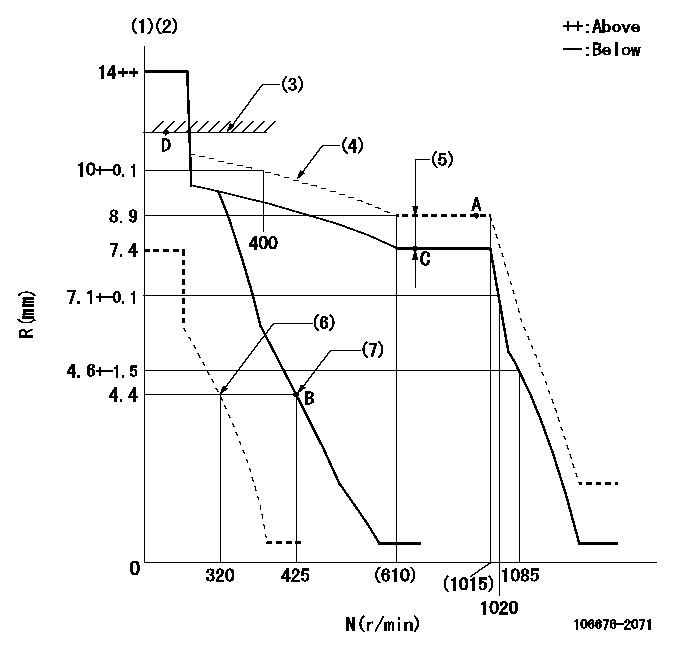
N:Pump speed
R:Rack position (mm)
(1)Notch fixed: K
(2)Tolerance for racks not indicated: +-0.05mm.
(3)RACK LIMIT
(4)The torque control spring must does not have a set force.
(5)Boost compensator stroke: BCL
(6)Set idle sub-spring
(7)Main spring setting
----------
K=12 BCL=1.25+-0.1mm
----------
----------
K=12 BCL=1.25+-0.1mm
----------
Speed control lever angle
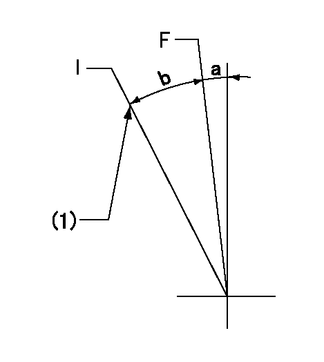
F:Full speed
I:Idle
(1)Stopper bolt setting
----------
----------
a=(4deg)+-5deg b=(14deg)+-5deg
----------
----------
a=(4deg)+-5deg b=(14deg)+-5deg
Stop lever angle
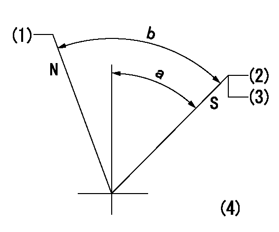
N:Pump normal
S:Stop the pump.
(1)Set the outer screw where it contacts the inside (seal at delivery)
(2)Pump speed aa and rack position bb (to be sealed at delivery)
(3)Stopper bolt setting
(4)No return spring
----------
aa=0r/min bb=1-0.5mm
----------
a=55deg+-5deg b=70deg+-5deg
----------
aa=0r/min bb=1-0.5mm
----------
a=55deg+-5deg b=70deg+-5deg
Timing setting

(1)Pump vertical direction
(2)Coupling's key groove position at No 1 cylinder's beginning of injection
(3)B.T.D.C.: aa
(4)-
----------
aa=12deg
----------
a=(6deg)
----------
aa=12deg
----------
a=(6deg)
Information:
New Part Number Reman Part Number Description Applications
212-3468 10R1258 Injector GP - Fuel C12 Ind, EuroIII Trk & Machine
212-3467 10R-1259 Injector GP - Fuel C10 & C12 Ind & Mach PELJ0171-01 © 2003 Caterpillar REM03-11A 2
Features And Benefits
Cat® Remanufactured injectors offer excellent value to customers. Customers who want fast repair turn-around, superior quality and reliability, and lower repair costs will benefit from the use of these Remanufactured injectors. Cat Remanufactured injectors provide immediate, off-the-shelf availability at a fraction of the new price.
Features Benefits
? ? ? ? ? ? All critical engineering changes and updates included
Improved reliability and performance
Worldwide availability through Caterpillar® parts distribution system Customer access regardless of location
Backed by Cat warranty Consistent support
Core Acceptance
Core Acceptance Criteria for Caterpillar Remanufactured injectors is simple, visual, and requires no special tools. Full core credit is issued when the core is complete, fully assembled, and has an acceptable part number. Consult your Core Acceptance Guide for complete details.
Warranty
Please consult the appropriate warranty statement for your area.
Core Management
Please refer to the Caterpillar Core Management Information System (CMIS 2) Parts Information application describing all reman part/CAF and related information. Also refer to other CMIS 2 inquiry applications such as Customer Profiles, Inspection Reason Codes, Inspection Line Inquiry, Add Charge Information, Entitlement Activity, Entitlement Inquiry, CCR Inquiry, CCR Entry, Shipment Processing; Process Packaging Grief; and Reporting to properly manage core returns and monitor inspection performance. This information will be available to all dealers worldwide after your CMIS 2 conversion date. In the meantime, please continue to use the current CMIS Entitlement Parts Inquiry Screen describing the list of parts in a Core Acceptability Family (CAF) and related part number detail.
IRM\304090313A.DOC REM03-11A 3
For the latest updates of Reman Policies and Core Management (SELD0122), Core Management Systems & Operations Procedures (SELD0040), and Shipping Instructions (SELD0039), go to the Reman Dealer website https://reman.cat.com
If you have any questions regarding core return processing, feel free to call Corinth
Have questions with 106676-2071?
Group cross 106676-2071 ZEXEL
Mitsubishi
Mitsubishi
Mitsubishi
Mitsubishi
Mitsubishi
Mitsubishi
106676-2071
9 400 617 427
ME158579
INJECTION-PUMP ASSEMBLY
6D24T
6D24T