Information injection-pump assembly
BOSCH
9 400 617 426
9400617426
ZEXEL
106676-2050
1066762050
MITSUBISHI
ME152784
me152784

Rating:
Cross reference number
BOSCH
9 400 617 426
9400617426
ZEXEL
106676-2050
1066762050
MITSUBISHI
ME152784
me152784
Zexel num
Bosch num
Firm num
Name
106676-2050
9 400 617 426
ME152784 MITSUBISHI
INJECTION-PUMP ASSEMBLY
6D22T2 K 14CA INJECTION PUMP ASSY PE6P,6PD PE
6D22T2 K 14CA INJECTION PUMP ASSY PE6P,6PD PE
Calibration Data:
Adjustment conditions
Test oil
1404 Test oil ISO4113 or {SAEJ967d}
1404 Test oil ISO4113 or {SAEJ967d}
Test oil temperature
degC
40
40
45
Nozzle and nozzle holder
105780-8250
Bosch type code
1 688 901 101
Nozzle
105780-0120
Bosch type code
1 688 901 990
Nozzle holder
105780-2190
Opening pressure
MPa
20.7
Opening pressure
kgf/cm2
211
Injection pipe
Outer diameter - inner diameter - length (mm) mm 8-3-600
Outer diameter - inner diameter - length (mm) mm 8-3-600
Overflow valve
131425-0220
Overflow valve opening pressure
kPa
157
123
191
Overflow valve opening pressure
kgf/cm2
1.6
1.25
1.95
Tester oil delivery pressure
kPa
255
255
255
Tester oil delivery pressure
kgf/cm2
2.6
2.6
2.6
Direction of rotation (viewed from drive side)
Right R
Right R
Injection timing adjustment
Direction of rotation (viewed from drive side)
Right R
Right R
Injection order
1-5-3-6-
2-4
Pre-stroke
mm
3.9
3.85
3.95
Beginning of injection position
Governor side NO.1
Governor side NO.1
Difference between angles 1
Cal 1-5 deg. 60 59.5 60.5
Cal 1-5 deg. 60 59.5 60.5
Difference between angles 2
Cal 1-3 deg. 120 119.5 120.5
Cal 1-3 deg. 120 119.5 120.5
Difference between angles 3
Cal 1-6 deg. 180 179.5 180.5
Cal 1-6 deg. 180 179.5 180.5
Difference between angles 4
Cyl.1-2 deg. 240 239.5 240.5
Cyl.1-2 deg. 240 239.5 240.5
Difference between angles 5
Cal 1-4 deg. 300 299.5 300.5
Cal 1-4 deg. 300 299.5 300.5
Injection quantity adjustment
Adjusting point
-
Rack position
13.2
Pump speed
r/min
650
650
650
Each cylinder's injection qty
mm3/st.
153.5
149.7
157.3
Basic
*
Fixing the rack
*
Standard for adjustment of the maximum variation between cylinders
*
Injection quantity adjustment_02
Adjusting point
Z
Rack position
8.6+-0.5
Pump speed
r/min
360
360
360
Each cylinder's injection qty
mm3/st.
15.8
13.4
18.2
Fixing the rack
*
Standard for adjustment of the maximum variation between cylinders
*
Injection quantity adjustment_03
Adjusting point
A
Rack position
R1(13.2)
Pump speed
r/min
650
650
650
Average injection quantity
mm3/st.
153.5
152.5
154.5
Basic
*
Fixing the lever
*
Boost pressure
kPa
25.3
25.3
Boost pressure
mmHg
190
190
Injection quantity adjustment_04
Adjusting point
B
Rack position
R1+1.4
Pump speed
r/min
1100
1100
1100
Average injection quantity
mm3/st.
151.5
147.5
155.5
Fixing the lever
*
Boost pressure
kPa
25.3
25.3
Boost pressure
mmHg
190
190
Injection quantity adjustment_05
Adjusting point
D
Rack position
R3-1.4
Pump speed
r/min
300
300
300
Average injection quantity
mm3/st.
90
86
94
Fixing the lever
*
Boost pressure
kPa
0
0
0
Boost pressure
mmHg
0
0
0
Injection quantity adjustment_06
Adjusting point
G
Rack position
(R1-2.35
)
Pump speed
r/min
400
400
400
Average injection quantity
mm3/st.
106
100
112
Fixing the lever
*
Boost pressure
kPa
0
0
0
Boost pressure
mmHg
0
0
0
Boost compensator adjustment
Pump speed
r/min
300
300
300
Rack position
R3-1.4
Boost pressure
kPa
5.3
4.6
6
Boost pressure
mmHg
40
35
45
Boost compensator adjustment_02
Pump speed
r/min
300
300
300
Rack position
R3(R1-1.
3)
Boost pressure
kPa
12
12
12
Boost pressure
mmHg
90
90
90
Timer adjustment
Pump speed
r/min
750--
Advance angle
deg.
0
0
0
Remarks
Start
Start
Timer adjustment_02
Pump speed
r/min
700
Advance angle
deg.
0.5
Timer adjustment_03
Pump speed
r/min
1100
Advance angle
deg.
4
3.5
4.5
Remarks
Finish
Finish
Test data Ex:
Governor adjustment
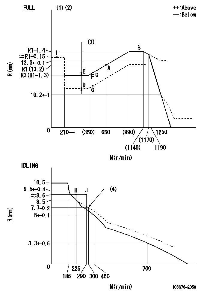
N:Pump speed
R:Rack position (mm)
(1)Torque cam stamping: T1
(2)Tolerance for racks not indicated: +-0.05mm.
(3)Boost compensator stroke: BCL
(4)Damper spring setting
----------
T1=AD44 BCL=1.4+-0.1mm
----------
----------
T1=AD44 BCL=1.4+-0.1mm
----------
Speed control lever angle
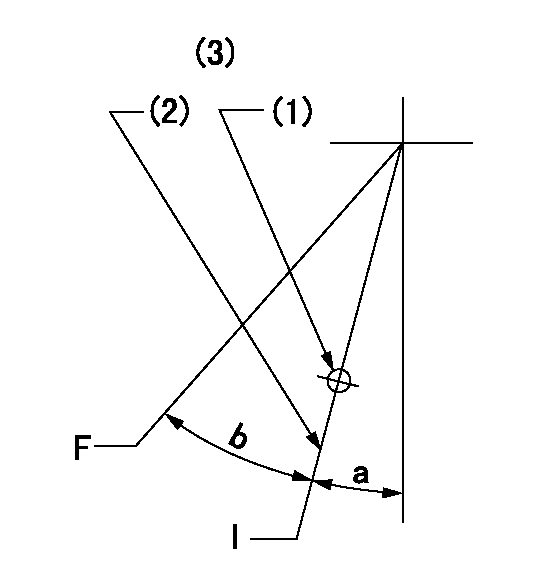
F:Full speed
I:Idle
(1)Use the hole at R = aa
(2)Stopper bolt set position 'H'
(3)Viewed from feed pump side.
----------
aa=43.5mm
----------
a=1deg+-5deg b=39deg+-3deg
----------
aa=43.5mm
----------
a=1deg+-5deg b=39deg+-3deg
Stop lever angle
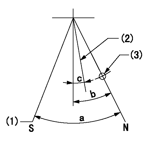
N:Pump normal
S:Stop the pump.
(1)At pump speed aa and rack position bb, set the stopper bolt. (Confirm non-injection.)
(2)Normal engine position (Rack position corresponding to cc)
(3)Use the hole above R = dd
----------
aa=1100r/min bb=3.5+-0.3mm cc=18mm dd=31.5mm
----------
a=41deg+-5deg b=34deg+-5deg c=(24deg)+-5deg
----------
aa=1100r/min bb=3.5+-0.3mm cc=18mm dd=31.5mm
----------
a=41deg+-5deg b=34deg+-5deg c=(24deg)+-5deg
0000001501 MICRO SWITCH
Adjustment of the micro-switch
Adjust the bolt to obtain the following lever position when the micro-switch is ON.
(1)Speed N1
(2)Rack position Ra
----------
N1=325r/min Ra=8.1+-0.1mm
----------
----------
N1=325r/min Ra=8.1+-0.1mm
----------
Timing setting

(1)Pump vertical direction
(2)Coupling's key groove position at No 1 cylinder's beginning of injection
(3)B.T.D.C.: aa
(4)-
----------
aa=8deg
----------
a=(2deg)
----------
aa=8deg
----------
a=(2deg)
Information:
REM02-46
Reman
November 2002 REMANUFACTURED FUEL INJECTORS FOR VARIOUS INDUSTRIAL, MACHINE, MARINE AND ON-HIGHWAY TRUCK APPLICATIONS Announcement The Caterpillar Remanufactured Products Group announces the expansion of the remanufactured injector product line to include coverage for various C10, C12, 3176, 3196, 3406E, 3456, C15, C16, and C18 Industrial, Machine, Marine and On-Highway Truck applications. Coverage The addition of these injectors provides dealers with an additional repair option to support various C10, C12, 3176, 3196, 3406E, 3456, C15, C16, and C18 Industrial, Machine, Marine and On-Highway Truck applications where low sulfur fuel is present. Coverage is extensive so please consult your NPR or Reman Cross Reference for exact model coverage. See the matrix on page two for part numbers and cross-reference information. Features And Benefits Features
All critical engineering changes and updates included
Worldwide availability through Caterpillar? parts distribution system
Backed by Cat warranty Benefits
Improved reliability and performance
Customer access regardless of location
Consistent support Core Acceptance Core Acceptance Criteria for Caterpillar Remanufactured injectors is simple, visual, and requires no special tools. Full core credit is issued when the core is complete, fully assembled, and has an acceptable part number. Consult your Core Acceptance Guide for complete details. Warranty Please consult the appropriate warranty statement for your area. Core Management Please refer to the Caterpillar Core Management Information System (CMIS 2) Parts Information application describing all reman part/CAF and related information. Also refer to other CMIS 2 inquiry applications such as Customer Profiles, Inspection Reason Codes, Inspection Line Inquiry, Add Charge Information, Entitlement Activity, Entitlement Inquiry, CCR Inquiry, CCR Entry, Shipment Processing; Process Packaging Grief; and Reporting to properly manage core returns and monitor inspection performance. This information will be available to all dealers worldwide after your CMIS 2 conversion date. In the meantime, please continue to use the current CMIS Entitlement Parts Inquiry Screen describing the list of parts in a Core Acceptability Family (CAF) and related part number detail. For the latest updates of Reman Policies and Core Management (SELD0122), Core Management Systems & Operations Procedures (SELD0040), and Shipping Instructions (SELD0039), go to the Reman website and click on Procedures and Policies (listed under Reman Program Information). If you have any questions regarding core return processing, feel free to call your Corinth Dealer Service Representative toll free at (800) 537-2928 or use our e-mail address -- reman_core_operations. For assistance with technical questions, call the Peoria Reman Customer Satisfaction Hot Line also toll free at (888) 88-REMAN or use our e-mail address--Reman_Help.
PELE0956 CATERPILLAR? ?2002 Caterpillar
Have questions with 106676-2050?
Group cross 106676-2050 ZEXEL
Mitsubishi
Mitsubishi
Mitsubishi
Mitsubishi
106676-2050
9 400 617 426
ME152784
INJECTION-PUMP ASSEMBLY
6D22T2
6D22T2