Information injection-pump assembly
ZEXEL
106676-2030
1066762030
Rating:
Cross reference number
ZEXEL
106676-2030
1066762030
Zexel num
Bosch num
Firm num
Name
106676-2030
INJECTION-PUMP ASSEMBLY
Calibration Data:
Adjustment conditions
Test oil
1404 Test oil ISO4113 or {SAEJ967d}
1404 Test oil ISO4113 or {SAEJ967d}
Test oil temperature
degC
40
40
45
Nozzle and nozzle holder
105780-8140
Bosch type code
EF8511/9A
Nozzle
105780-0000
Bosch type code
DN12SD12T
Nozzle holder
105780-2080
Bosch type code
EF8511/9
Opening pressure
MPa
17.2
Opening pressure
kgf/cm2
175
Injection pipe
Outer diameter - inner diameter - length (mm) mm 8-3-600
Outer diameter - inner diameter - length (mm) mm 8-3-600
Overflow valve
131424-4620
Overflow valve opening pressure
kPa
255
221
289
Overflow valve opening pressure
kgf/cm2
2.6
2.25
2.95
Tester oil delivery pressure
kPa
157
157
157
Tester oil delivery pressure
kgf/cm2
1.6
1.6
1.6
Direction of rotation (viewed from drive side)
Right R
Right R
Injection timing adjustment
Direction of rotation (viewed from drive side)
Right R
Right R
Injection order
1-5-3-6-
2-4
Pre-stroke
mm
4.8
4.75
4.85
Beginning of injection position
Governor side NO.1
Governor side NO.1
Difference between angles 1
Cal 1-5 deg. 60 59.5 60.5
Cal 1-5 deg. 60 59.5 60.5
Difference between angles 2
Cal 1-3 deg. 120 119.5 120.5
Cal 1-3 deg. 120 119.5 120.5
Difference between angles 3
Cal 1-6 deg. 180 179.5 180.5
Cal 1-6 deg. 180 179.5 180.5
Difference between angles 4
Cyl.1-2 deg. 240 239.5 240.5
Cyl.1-2 deg. 240 239.5 240.5
Difference between angles 5
Cal 1-4 deg. 300 299.5 300.5
Cal 1-4 deg. 300 299.5 300.5
Injection quantity adjustment
Adjusting point
A
Rack position
10.1
Pump speed
r/min
1100
1100
1100
Average injection quantity
mm3/st.
146
143
149
Max. variation between cylinders
%
0
-3
3
Basic
*
Fixing the lever
*
Injection quantity adjustment_02
Adjusting point
B
Rack position
5.5+-0.5
Pump speed
r/min
325
325
325
Average injection quantity
mm3/st.
13
10.4
15.6
Max. variation between cylinders
%
0
-15
15
Fixing the rack
*
Injection quantity adjustment_03
Adjusting point
C
Rack position
-
Pump speed
r/min
100
100
100
Average injection quantity
mm3/st.
130
110
150
Fixing the lever
*
Rack limit
*
Timer adjustment
Pump speed
r/min
750--
Advance angle
deg.
0
0
0
Load
0/4
Remarks
Beginning of advance.
Beginning of advance.
Timer adjustment_02
Pump speed
r/min
300
Load
4/4
Remarks
Measure the actual advance angle (beginning of advance).
Measure the actual advance angle (beginning of advance).
Timer adjustment_03
Pump speed
r/min
-
Advance angle
deg.
0
0
0
Load
4/4
Remarks
Measure the actual speed.
Measure the actual speed.
Timer adjustment_04
Pump speed
r/min
-
Advance angle
deg.
0
0
0
Load
4/4
Remarks
Measure the actual speed.
Measure the actual speed.
Timer adjustment_05
Pump speed
r/min
900
Advance angle
deg.
2.5
2
3
Load
4/4
Remarks
Finish
Finish
Test data Ex:
Governor adjustment
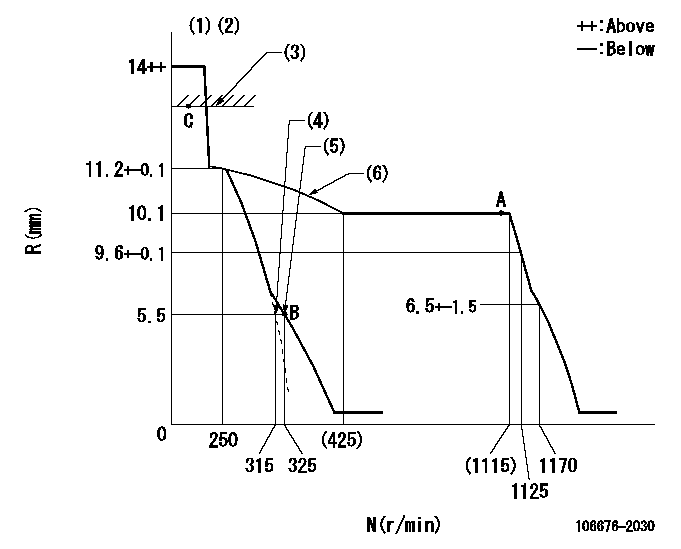
N:Pump speed
R:Rack position (mm)
(1)Notch fixed: K
(2)Tolerance for racks not indicated: +-0.05mm.
(3)RACK LIMIT
(4)Main spring setting
(5)Set idle sub-spring
(6)The torque control spring must does not have a set force.
----------
K=8
----------
----------
K=8
----------
Speed control lever angle

F:Full speed
I:Idle
(1)Stopper bolt setting
----------
----------
a=(25deg)+-5deg b=(4deg)+-5deg
----------
----------
a=(25deg)+-5deg b=(4deg)+-5deg
Stop lever angle
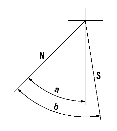
N:Pump normal
S:Stop the pump.
----------
----------
a=43.5deg+-5deg b=53deg+-5deg
----------
----------
a=43.5deg+-5deg b=53deg+-5deg
Timing setting

(1)Pump vertical direction
(2)Coupling's key groove position at No 1 cylinder's beginning of injection
(3)B.T.D.C.: aa
(4)-
----------
aa=10deg
----------
a=(5deg)
----------
aa=10deg
----------
a=(5deg)
Information:
Problem
Some remanufactured fuel injection pumps have been built with the control solenoid in the wrong position. If the solenoid is in the wrong position, the wiring harness may be impossible to connect to the solenoid due to interference of other components.The affected fuel pump part numbers are:
10R-7659 Unit Injection Hydraulic Pump and Mounting Gp
10R-7660 Unit Injection Hydraulic Pump and Mounting Gp
10R-7661 Unit Injection Hydraulic Pump and Mounting Gp
10R-7662 Fuel Pump Gp
20R-3815 Fuel Injection Pump GpSolution
Illustration 1 g06120812
View of the top of the 10R-7661 Unit Injection Hydraulic Pump and Mounting Gp and 10R-7662 Fuel Pump Gp.
(X) Pump center line
(Y) Acceptable solenoid connector orientation (—30 degrees to 30 degrees from pump center line)
Illustration 2 g06120817
View of the top of the 10R-7659 Unit Injection Hydraulic Pump and Mounting Gp, 10R-7660 Unit Injection Hydraulic Pump and Mounting Gp, and 20R-3815 Fuel Injection Pump Gp.
(X) Pump center line
(Z) Acceptable solenoid connector orientation (15 degrees to 45 degrees from pump center line)Check the fuel injection pump solenoid position before attempting to install the pump. Refer to Illustration 1 and Illustration 2. If the orientation of the connector on the solenoid is not within the acceptable range, return the faulty pump and replace the pump with the same part number.Note: Do not attempt to disassemble the fuel injection pump to reposition the solenoid.
Have questions with 106676-2030?
Group cross 106676-2030 ZEXEL
Mitsubishi
Mitsubishi
106676-2030
INJECTION-PUMP ASSEMBLY