Information injection-pump assembly
BOSCH
9 400 617 418
9400617418
ZEXEL
106675-4790
1066754790
KOMATSU
6211721180
6211721180

Rating:
Service parts 106675-4790 INJECTION-PUMP ASSEMBLY:
1.
_
5.
AUTOM. ADVANCE MECHANIS
7.
COUPLING PLATE
8.
_
9.
_
11.
Nozzle and Holder
12.
Open Pre:MPa(Kqf/cm2)
24.5[250}
15.
NOZZLE SET
Include in #1:
106675-4790
as INJECTION-PUMP ASSEMBLY
Cross reference number
BOSCH
9 400 617 418
9400617418
ZEXEL
106675-4790
1066754790
KOMATSU
6211721180
6211721180
Zexel num
Bosch num
Firm num
Name
106675-4790
9 400 617 418
6211721180 KOMATSU
INJECTION-PUMP ASSEMBLY
SA6D140 K 14CA INJECTION PUMP ASSY PE6P,6PD PE
SA6D140 K 14CA INJECTION PUMP ASSY PE6P,6PD PE
Calibration Data:
Adjustment conditions
Test oil
1404 Test oil ISO4113 or {SAEJ967d}
1404 Test oil ISO4113 or {SAEJ967d}
Test oil temperature
degC
40
40
45
Nozzle and nozzle holder
105780-8140
Bosch type code
EF8511/9A
Nozzle
105780-0000
Bosch type code
DN12SD12T
Nozzle holder
105780-2080
Bosch type code
EF8511/9
Opening pressure
MPa
17.2
Opening pressure
kgf/cm2
175
Injection pipe
Outer diameter - inner diameter - length (mm) mm 8-3-600
Outer diameter - inner diameter - length (mm) mm 8-3-600
Overflow valve
131424-3420
Overflow valve opening pressure
kPa
255
221
289
Overflow valve opening pressure
kgf/cm2
2.6
2.25
2.95
Tester oil delivery pressure
kPa
255
255
255
Tester oil delivery pressure
kgf/cm2
2.6
2.6
2.6
Direction of rotation (viewed from drive side)
Right R
Right R
Injection timing adjustment
Direction of rotation (viewed from drive side)
Right R
Right R
Injection order
1-5-3-6-
2-4
Pre-stroke
mm
3.9
3.85
3.95
Beginning of injection position
Drive side NO.1
Drive side NO.1
Difference between angles 1
Cal 1-5 deg. 60 59.5 60.5
Cal 1-5 deg. 60 59.5 60.5
Difference between angles 2
Cal 1-3 deg. 120 119.5 120.5
Cal 1-3 deg. 120 119.5 120.5
Difference between angles 3
Cal 1-6 deg. 180 179.5 180.5
Cal 1-6 deg. 180 179.5 180.5
Difference between angles 4
Cyl.1-2 deg. 240 239.5 240.5
Cyl.1-2 deg. 240 239.5 240.5
Difference between angles 5
Cal 1-4 deg. 300 299.5 300.5
Cal 1-4 deg. 300 299.5 300.5
Injection quantity adjustment
Adjusting point
A
Rack position
10.2
Pump speed
r/min
1000
1000
1000
Average injection quantity
mm3/st.
143
140
146
Max. variation between cylinders
%
0
-3
3
Basic
*
Fixing the lever
*
Boost pressure
kPa
51.3
51.3
Boost pressure
mmHg
385
385
Injection quantity adjustment_02
Adjusting point
-
Rack position
7.2+-0.5
Pump speed
r/min
360
360
360
Average injection quantity
mm3/st.
23
21.5
24.5
Max. variation between cylinders
%
0
-15
15
Fixing the rack
*
Boost pressure
kPa
0
0
0
Boost pressure
mmHg
0
0
0
Remarks
Adjust only variation between cylinders; adjust governor according to governor specifications.
Adjust only variation between cylinders; adjust governor according to governor specifications.
Injection quantity adjustment_03
Adjusting point
E
Rack position
10.4++
Pump speed
r/min
100
100
100
Average injection quantity
mm3/st.
160
150
170
Fixing the lever
*
Boost pressure
kPa
0
0
0
Boost pressure
mmHg
0
0
0
Rack limit
*
Boost compensator adjustment
Pump speed
r/min
600
600
600
Rack position
R1-0.95
Boost pressure
kPa
18
15.3
20.7
Boost pressure
mmHg
135
115
155
Boost compensator adjustment_02
Pump speed
r/min
600
600
600
Rack position
R1(10.2)
Boost pressure
kPa
38
31.3
44.7
Boost pressure
mmHg
285
235
335
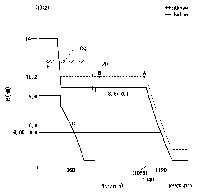
Test data Ex:
Governor adjustment

N:Pump speed
R:Rack position (mm)
(1)Target notch: K
(2)Tolerance for racks not indicated: +-0.05mm.
(3)RACK LIMIT
(4)Boost compensator stroke: BCL
----------
K=15 BCL=0.95+-0.1mm
----------
----------
K=15 BCL=0.95+-0.1mm
----------
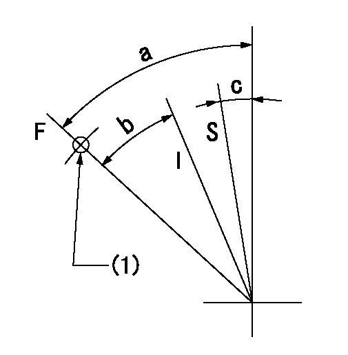
Speed control lever angle

F:Full speed
I:Idle
S:Stop
(1)Use the hole at R = aa
----------
aa=90mm
----------
a=(50deg)+-5deg b=(20deg)+-5deg c=2deg+-3deg
----------
aa=90mm
----------
a=(50deg)+-5deg b=(20deg)+-5deg c=2deg+-3deg
Timing setting

(1)Pump vertical direction
(2)Coupling's key groove position at No 1 cylinder's beginning of injection
(3)-
(4)-
----------
----------
a=(10deg)
----------
----------
a=(10deg)
Information:
The purpose of the air induction system is to provide clean air to the engine in an efficient, unrestricted, silent manner while the exhaust system discharges exhaust gases as quickly and as silently as possible with minimum backpressure. Engine horsepower and efficiently will be reduced if either the air inlet or exhaust becomes restricted. Good maintenance practice cannot be over emphasized. AIR CLEANERS: Regular service intervals, along with close visual inspection of the air cleaner, are necessary for proper cleaning of the engine inlet air. The service interval will vary with the weather and working conditions. Where dust conditions are severe, it will be necessary to service the air cleaner frequently. In damp weather and other conditions of little or no dust, the service interval can be extended.To extend the service life of the element, the exhaust and air cleaner inlet pipes should be arranged so that exhaust and/or oil fumes do not enter the engine air cleaner.Visual inspection of the gaskets and seals is important in keeping dust from by-passing the air cleaner. Any dirt allowed to enter, accelerates wear throughout the engine. If the condition of any of the replaceable seals and gaskets is questionable, replace them. If the sealing ends of the filter element or the element pleats are damaged. replace the element.Extra filter elements should be kept on hand for replacement or for use in the air cleaner while the element that was removed is being cleaned.When equipped with a dry-type air cleaner, a service indicator similar to the one shown is available. The air cleaner service indicator is connected to the air inlet pipe between the air cleaner and the manifold. It contains a red marked piston, which gradually rises with restriction to the air flow. When the entire piston is visible it will lock in this position. This indicates a need for air cleaner service. The piston will remain in this position whether or not the engine is running. After servicing the air cleaner, reset the piston by depressing the plunger in the bottom of the indicator.Excessive engine exhaust smoke and/or loss of power may indicate the need for servicing the air cleaner. Never service the air cleaner while the engine is running.(See your truck manufacturer's operator's books for maintenance intervals and instructions.) Air cleaner restriction at high idle should not exceed 25 inches (635 mm) of water.Valve Lash
Make valve lash adjustment with engine stopped.Top dead center (TDC) of the No. 1 piston on the compression stroke is the reference point. The No. 1 piston is at TDC compression stroke when the timing mark on the crankshaft damper or the pulley is aligned with the timing pointer, and No. 1 and No. 2 exhaust and inlet valves are closed. (The rocker arms are free.) To Adjust The Valve Lash
1. Adjust lash for No. 1 and No. 2 exhaust and inlet valves. a. Loosen valve adjusting screw locknut.b. Turn adjusting screw to allow a clearance gauge to pass between the top of
Have questions with 106675-4790?
Group cross 106675-4790 ZEXEL
Komatsu
Komatsu
Komatsu
Komatsu
Komatsu
Komatsu
Komatsu
Komatsu
Komatsu
Komatsu
Niigata-Urawa
Niigata-Tekkou
Komatsu
106675-4790
9 400 617 418
6211721180
INJECTION-PUMP ASSEMBLY
SA6D140
SA6D140