Information injection-pump assembly
ZEXEL
106675-4780
1066754780
NIIGATA-URAWA
75G47230A
75g47230a
Rating:
Service parts 106675-4780 INJECTION-PUMP ASSEMBLY:
1.
_
5.
AUTOM. ADVANCE MECHANIS
7.
COUPLING PLATE
8.
_
9.
_
10.
NOZZLE AND HOLDER ASSY
11.
Nozzle and Holder
12.
Open Pre:MPa(Kqf/cm2)
29.4(300)
15.
NOZZLE SET
Include in #1:
106675-4780
as INJECTION-PUMP ASSEMBLY
Cross reference number
ZEXEL
106675-4780
1066754780
NIIGATA-URAWA
75G47230A
75g47230a
Zexel num
Bosch num
Firm num
Name
Calibration Data:
Adjustment conditions
Test oil
1404 Test oil ISO4113 or {SAEJ967d}
1404 Test oil ISO4113 or {SAEJ967d}
Test oil temperature
degC
40
40
45
Nozzle and nozzle holder
105780-8130
Bosch type code
EFEP215A
Nozzle
105780-0050
Bosch type code
DN6TD119NP1T
Nozzle holder
105780-2090
Bosch type code
EFEP215
Opening pressure
MPa
17.2
Opening pressure
kgf/cm2
175
Injection pipe
Outer diameter - inner diameter - length (mm) mm 8-3-600
Outer diameter - inner diameter - length (mm) mm 8-3-600
Overflow valve
131425-0120
Overflow valve opening pressure
kPa
157
123
191
Overflow valve opening pressure
kgf/cm2
1.6
1.25
1.95
Tester oil delivery pressure
kPa
157
157
157
Tester oil delivery pressure
kgf/cm2
1.6
1.6
1.6
Direction of rotation (viewed from drive side)
Left L
Left L
Injection timing adjustment
Direction of rotation (viewed from drive side)
Left L
Left L
Injection order
1-4-2-6-
3-5
Pre-stroke
mm
3.9
3.85
3.95
Beginning of injection position
Drive side NO.1
Drive side NO.1
Difference between angles 1
Cal 1-4 deg. 60 59.5 60.5
Cal 1-4 deg. 60 59.5 60.5
Difference between angles 2
Cyl.1-2 deg. 120 119.5 120.5
Cyl.1-2 deg. 120 119.5 120.5
Difference between angles 3
Cal 1-6 deg. 180 179.5 180.5
Cal 1-6 deg. 180 179.5 180.5
Difference between angles 4
Cal 1-3 deg. 240 239.5 240.5
Cal 1-3 deg. 240 239.5 240.5
Difference between angles 5
Cal 1-5 deg. 300 299.5 300.5
Cal 1-5 deg. 300 299.5 300.5
Injection quantity adjustment
Adjusting point
A
Rack position
15.1
Pump speed
r/min
600
600
600
Average injection quantity
mm3/st.
287
282
292
Max. variation between cylinders
%
0
-3
3
Basic
*
Fixing the rack
*
Injection quantity adjustment_02
Adjusting point
B
Rack position
5.7+-0.5
Pump speed
r/min
250
250
250
Average injection quantity
mm3/st.
44.5
41.5
47.5
Fixing the rack
*
Injection quantity adjustment_03
Adjusting point
-
Rack position
5.2+-0.5
Pump speed
r/min
620
620
620
Average injection quantity
mm3/st.
45.5
42.5
48.5
Max. variation between cylinders
%
0
-10
10
Fixing the rack
*
Remarks
Adjust only variation between cylinders; adjust governor according to governor specifications.
Adjust only variation between cylinders; adjust governor according to governor specifications.
Test data Ex:
Governor adjustment
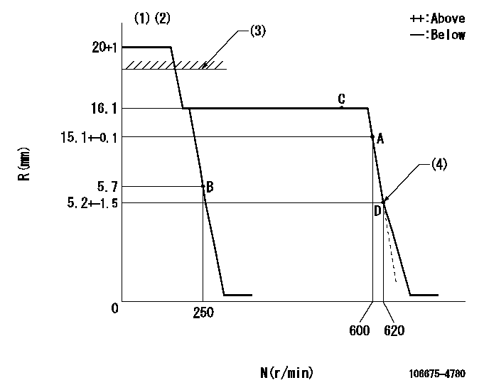
N:Pump speed
R:Rack position (mm)
(1)Target notch: K
(2)Tolerance for racks not indicated: +-0.05mm.
(3)RACK LIMIT: RAL
(4)Idle sub spring setting: L1.
----------
K=5 RAL=17.5+0.5mm L1=5.2-0.5mm
----------
----------
K=5 RAL=17.5+0.5mm L1=5.2-0.5mm
----------
Speed control lever angle
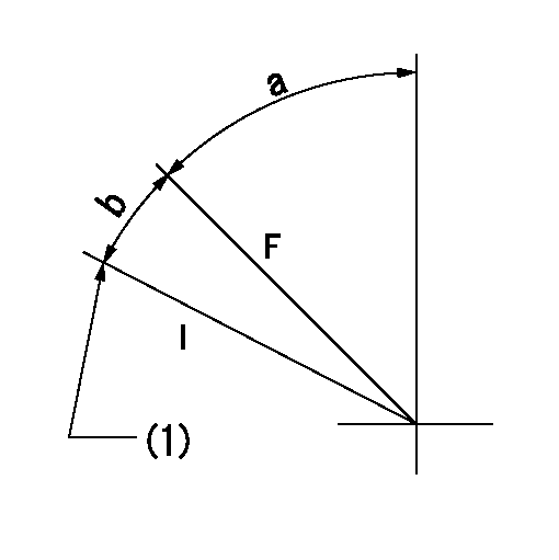
F:Full speed
I:Idle
(1)Stopper bolt setting
----------
----------
a=37deg+-5deg b=26deg+-5deg
----------
----------
a=37deg+-5deg b=26deg+-5deg
Stop lever angle
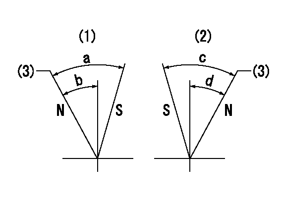
N:Pump normal
S:Stop the pump.
(1)Right front
(2)Right rear
(3)Normal
----------
----------
a=47deg+-5deg b=33deg+-5deg c=53deg+-5deg d=36deg+-5deg
----------
----------
a=47deg+-5deg b=33deg+-5deg c=53deg+-5deg d=36deg+-5deg
Timing setting

(1)Pump vertical direction
(2)Coupling's key groove position for the No. 6 cylinder's beginning of injection
(3)B.T.D.C.: aa
(4)-
----------
aa=16deg
----------
a=(6deg)
----------
aa=16deg
----------
a=(6deg)
Information:
General Instructions
These instructions are a review of many items which a serviceman encounters in servicing and maintaining a truck engine.PROBLEM ANALYZING: In analyzing a system malfunction, use this systematic procedure to locate and correct the problem.1. Determine problem.2. List possible causes.3. Devise checks.4. Conduct checks in logical order to determine cause.5. Consider remaining service life against cost of parts and labor.6. Make necessary repair.7. Recheck.SAFETY: Your safety and that of others is always the number one consideration when servicing or maintaining trucks and truck engines. Safety is a matter of thoroughly understanding the job to be done and the application of good common sense. It is not just a matter of "do's" and "don'ts".CLEANLINESS: The most important single item in assuring long engine life is to keep dirt out of vital working parts. Precautions have been taken to safeguard against this. Enclosed compartments, seals and filters have been provided to keep the supply of air, fuel, coolant and lubricants clean. It is important that these safeguards be maintained.Whenever fuel, lubricating oil, coolant lines or air lines are disconnected, clean the point of disconnection as well as the adjacent area. As soon as the disconnection is made, cap, plug or tape the line or opening to prevent entry of foreign material. The same recommendations for cleaning and covering apply when access covers or inspection plates are removed.Clean and inspect all parts. Be sure all passages and holes are open. Cover all parts to keep them clean. Be sure parts are clean when they are installed. Leave new parts in their containers until ready for assembly.REMOVAL AND INSTALLATION: Use a hoist to remove heavy components. Engine removal should be accomplished by using an adjustable lifting beam. All supporting members (chains and cables) should be parallel to each other and as near perpendicular as possible to the top of the object being lifted. When it is necessary to remove a component on an angle, remember that the capacity of an eyebolt diminishes as the angle between the supporting members and the object becomes less than 90°. Eyebolts and brackets should never be bent and should only have stress in tension.Some removals require the use of lifting fixtures to obtain proper balance and to provide safe handling.If a part resists removal, check to be certain all nuts and bolts have been removed and that an adjacent part is not interfering.DISASSEMBLY AND ASSEMBLY: When servicing or repairing the engine, complete each step in turn. Do not partially assemble one part and start assembling some other part. Make all adjustments as recommended. Always check the job after it is completed to see nothing has been overlooked.BOLTS AND BOLT TORQUE: Use bolts of the correct length. A bolt which is too long may "bottom" before the head is tight against the part it is to hold and cause failure. The threads in the assembly can also become damaged when a "long" bolt is used.If a bolt is too short, there may not be enough threads
These instructions are a review of many items which a serviceman encounters in servicing and maintaining a truck engine.PROBLEM ANALYZING: In analyzing a system malfunction, use this systematic procedure to locate and correct the problem.1. Determine problem.2. List possible causes.3. Devise checks.4. Conduct checks in logical order to determine cause.5. Consider remaining service life against cost of parts and labor.6. Make necessary repair.7. Recheck.SAFETY: Your safety and that of others is always the number one consideration when servicing or maintaining trucks and truck engines. Safety is a matter of thoroughly understanding the job to be done and the application of good common sense. It is not just a matter of "do's" and "don'ts".CLEANLINESS: The most important single item in assuring long engine life is to keep dirt out of vital working parts. Precautions have been taken to safeguard against this. Enclosed compartments, seals and filters have been provided to keep the supply of air, fuel, coolant and lubricants clean. It is important that these safeguards be maintained.Whenever fuel, lubricating oil, coolant lines or air lines are disconnected, clean the point of disconnection as well as the adjacent area. As soon as the disconnection is made, cap, plug or tape the line or opening to prevent entry of foreign material. The same recommendations for cleaning and covering apply when access covers or inspection plates are removed.Clean and inspect all parts. Be sure all passages and holes are open. Cover all parts to keep them clean. Be sure parts are clean when they are installed. Leave new parts in their containers until ready for assembly.REMOVAL AND INSTALLATION: Use a hoist to remove heavy components. Engine removal should be accomplished by using an adjustable lifting beam. All supporting members (chains and cables) should be parallel to each other and as near perpendicular as possible to the top of the object being lifted. When it is necessary to remove a component on an angle, remember that the capacity of an eyebolt diminishes as the angle between the supporting members and the object becomes less than 90°. Eyebolts and brackets should never be bent and should only have stress in tension.Some removals require the use of lifting fixtures to obtain proper balance and to provide safe handling.If a part resists removal, check to be certain all nuts and bolts have been removed and that an adjacent part is not interfering.DISASSEMBLY AND ASSEMBLY: When servicing or repairing the engine, complete each step in turn. Do not partially assemble one part and start assembling some other part. Make all adjustments as recommended. Always check the job after it is completed to see nothing has been overlooked.BOLTS AND BOLT TORQUE: Use bolts of the correct length. A bolt which is too long may "bottom" before the head is tight against the part it is to hold and cause failure. The threads in the assembly can also become damaged when a "long" bolt is used.If a bolt is too short, there may not be enough threads