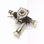
Information injection-pump assembly
BOSCH
F 019 Z10 245
f019z10245
ZEXEL
106675-4771
1066754771
Rating:
Service parts 106675-4771 INJECTION-PUMP ASSEMBLY:
1.
_
5.
AUTOM. ADVANCE MECHANIS
7.
COUPLING PLATE
8.
_
9.
_
11.
Nozzle and Holder
12.
Open Pre:MPa(Kqf/cm2)
27.5{280}
15.
NOZZLE SET
Include in #1:
106675-4771
as INJECTION-PUMP ASSEMBLY
Cross reference number
BOSCH
F 019 Z10 245
f019z10245
ZEXEL
106675-4771
1066754771
Zexel num
Bosch num
Firm num
Name
Calibration Data:
Adjustment conditions
Test oil
1404 Test oil ISO4113 or {SAEJ967d}
1404 Test oil ISO4113 or {SAEJ967d}
Test oil temperature
degC
40
40
45
Nozzle and nozzle holder
105780-8130
Bosch type code
EFEP215A
Nozzle
105780-0050
Bosch type code
DN6TD119NP1T
Nozzle holder
105780-2090
Bosch type code
EFEP215
Opening pressure
MPa
17.2
Opening pressure
kgf/cm2
175
Injection pipe
Outer diameter - inner diameter - length (mm) mm 8-3-600
Outer diameter - inner diameter - length (mm) mm 8-3-600
Overflow valve
131425-2120
Overflow valve opening pressure
kPa
157
157
157
Overflow valve opening pressure
kgf/cm2
1.6
1.6
1.6
Tester oil delivery pressure
kPa
157
157
157
Tester oil delivery pressure
kgf/cm2
1.6
1.6
1.6
Direction of rotation (viewed from drive side)
Left L
Left L
Injection timing adjustment
Direction of rotation (viewed from drive side)
Left L
Left L
Injection order
1-5-3-6-
2-4
Pre-stroke
mm
4.2
4.15
4.25
Rack position
Point A or more. R=A++
Point A or more. R=A++
Beginning of injection position
Drive side NO.1
Drive side NO.1
Difference between angles 1
Cal 1-5 deg. 60 59.5 60.5
Cal 1-5 deg. 60 59.5 60.5
Difference between angles 2
Cal 1-3 deg. 120 119.5 120.5
Cal 1-3 deg. 120 119.5 120.5
Difference between angles 3
Cal 1-6 deg. 180 179.5 180.5
Cal 1-6 deg. 180 179.5 180.5
Difference between angles 4
Cyl.1-2 deg. 240 239.5 240.5
Cyl.1-2 deg. 240 239.5 240.5
Difference between angles 5
Cal 1-4 deg. 300 299.5 300.5
Cal 1-4 deg. 300 299.5 300.5
Injection quantity adjustment
Adjusting point
A
Rack position
11.4
Pump speed
r/min
900
900
900
Average injection quantity
mm3/st.
321
318
324
Max. variation between cylinders
%
0
-3
3
Basic
*
Fixing the rack
*
Injection quantity adjustment_02
Adjusting point
C
Rack position
4.9+-0.5
Pump speed
r/min
375
375
375
Average injection quantity
mm3/st.
19
17.5
20.5
Max. variation between cylinders
%
0
-15
15
Fixing the rack
*
Test data Ex:
Governor adjustment
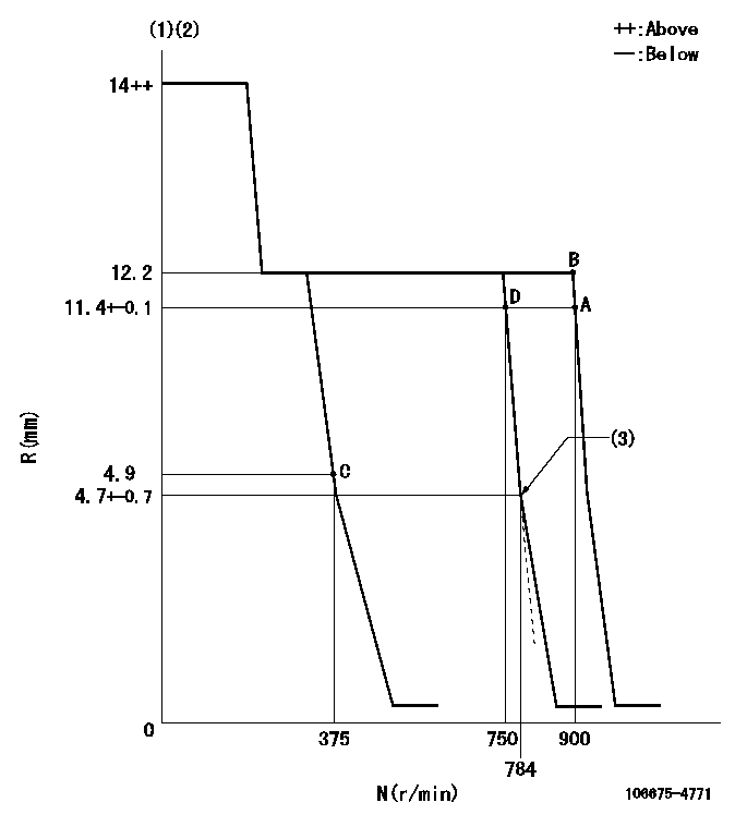
N:Pump speed
R:Rack position (mm)
(1)Target notch: K
(2)Tolerance for racks not indicated: +-0.05mm.
(3)Idle sub spring setting: L1.
----------
K=8 L1=4.7-0.5mm
----------
----------
K=8 L1=4.7-0.5mm
----------
Speed control lever angle
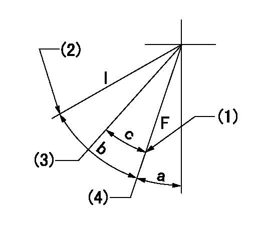
F:Full speed
I:Idle
(1)Stopper bolt setting
(2)Stopper bolt setting
(3)When pump speed set at aa
(4)Set the pump speed at bb.
----------
aa=750r/min bb=900r/min
----------
a=3deg+-5deg b=21deg+-5deg c=6deg+-5deg
----------
aa=750r/min bb=900r/min
----------
a=3deg+-5deg b=21deg+-5deg c=6deg+-5deg
Stop lever angle
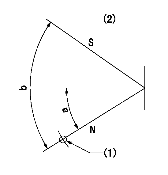
N:Pump normal
S:Stop the pump.
(1)Use hole at R = aa (left hand side)
(2)No return spring
----------
aa=27mm
----------
a=26.5deg+-5deg b=53deg+-5deg
----------
aa=27mm
----------
a=26.5deg+-5deg b=53deg+-5deg
Timing setting
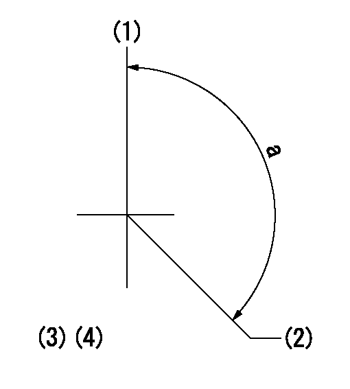
(1)Pump vertical direction
(2)Coupling's key groove position at No 1 cylinder's beginning of injection
(3)At rack position = at least aa
(4)-
----------
aa=11.4mm
----------
a=(140deg)
----------
aa=11.4mm
----------
a=(140deg)
Information:
CHECK CRANKCASE OIL LEVEL before starting and when refueling. The dipstick has 2 marks, and the distance between them represents 3 quarts. Always check oil with engine stopped and truck on level ground. Use oils meeting the following engine service classification:SC and SD (MS - Motor Severe Oils)CB (Supplement 1 Oils)CC (MIL-L-2104B or MIL-L-46152 Specification Oils)CD or MIL-L-2104CChange engine oil and filters as specified in the Lubrication and Maintenance Charts. CHECK ENGINE COOLANT LEVEL (with engine stopped). Always release cooling system pressure before checking. Fill to the proper level with water, free as possible from scale-forming minerals (not softened water), and rust inhibitor, or a solution of water and a permanent type anti-freeze containing rust inhibitor. It is recommended Caterpillar Coolant System Inhibitor be added to the coolant solution if protection is for temperatures above -20°F (-29°C). It is not necessary to add inhibitor to the coolant solution if protection is for temperatures -20°F (-29°C) and below.Models equipped with sight gauge; coolant should be warm (engine stopped) and coolant should be visible in the sight gauge.
Inhibitor contains alkali. Avoid contact with skin and eyes.
CHECK RADIATOR for dirt and foreign material, fan, water pump and accessory drive belts for cracks, breaks and frayed edges. While checking belts, also check for oil, water and fuel leaks and general appearance of engine and engine compartment. CHECK FUEL SUPPLY: Drain a cupful of fuel from the bottom of the tank to remove water or sediment.Fill fuel tanks after completing a run. Partially filled tanks will collect moisture if the truck is parked for any length of time. Use No. 2D diesel fuel in Caterpillar 1100 Series Diesel Truck Engines. Use No. 1-D diesel fuel in cold temperatures when white smoke must be minimized on start up. Keep fuel clean. Refer to Fuel Specifications for detailed information on fuel selection.
