Information injection-pump assembly
BOSCH
9 400 617 406
9400617406
ZEXEL
106675-4591
1066754591
Rating:
Cross reference number
BOSCH
9 400 617 406
9400617406
ZEXEL
106675-4591
1066754591
Zexel num
Bosch num
Firm num
Name
106675-4591
9 400 617 406
DAEWOO
INJECTION-PUMP ASSEMBLY
DE12TI K 14CA INJECTION PUMP ASSY PE6P,6PD PE
DE12TI K 14CA INJECTION PUMP ASSY PE6P,6PD PE
Calibration Data:
Adjustment conditions
Test oil
1404 Test oil ISO4113 or {SAEJ967d}
1404 Test oil ISO4113 or {SAEJ967d}
Test oil temperature
degC
40
40
45
Nozzle and nozzle holder
105780-8140
Bosch type code
EF8511/9A
Nozzle
105780-0000
Bosch type code
DN12SD12T
Nozzle holder
105780-2080
Bosch type code
EF8511/9
Opening pressure
MPa
17.2
Opening pressure
kgf/cm2
175
Injection pipe
Outer diameter - inner diameter - length (mm) mm 8-3-600
Outer diameter - inner diameter - length (mm) mm 8-3-600
Overflow valve
131424-4420
Overflow valve opening pressure
kPa
157
123
191
Overflow valve opening pressure
kgf/cm2
1.6
1.25
1.95
Tester oil delivery pressure
kPa
157
157
157
Tester oil delivery pressure
kgf/cm2
1.6
1.6
1.6
Direction of rotation (viewed from drive side)
Right R
Right R
Injection timing adjustment
Direction of rotation (viewed from drive side)
Right R
Right R
Injection order
1-5-3-6-
2-4
Pre-stroke
mm
4.2
4.15
4.25
Beginning of injection position
Governor side NO.1
Governor side NO.1
Difference between angles 1
Cal 1-5 deg. 60 59.5 60.5
Cal 1-5 deg. 60 59.5 60.5
Difference between angles 2
Cal 1-3 deg. 120 119.5 120.5
Cal 1-3 deg. 120 119.5 120.5
Difference between angles 3
Cal 1-6 deg. 180 179.5 180.5
Cal 1-6 deg. 180 179.5 180.5
Difference between angles 4
Cyl.1-2 deg. 240 239.5 240.5
Cyl.1-2 deg. 240 239.5 240.5
Difference between angles 5
Cal 1-4 deg. 300 299.5 300.5
Cal 1-4 deg. 300 299.5 300.5
Injection quantity adjustment
Adjusting point
A
Rack position
9.9
Pump speed
r/min
1050
1050
1050
Average injection quantity
mm3/st.
116.5
114.5
118.5
Max. variation between cylinders
%
0
-2
2
Basic
*
Fixing the lever
*
Injection quantity adjustment_02
Adjusting point
C
Rack position
7+-0.5
Pump speed
r/min
500
500
500
Average injection quantity
mm3/st.
19.5
18
21
Max. variation between cylinders
%
0
-15
15
Fixing the rack
*
Test data Ex:
Governor adjustment
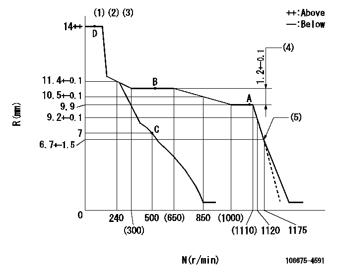
N:Pump speed
R:Rack position (mm)
(1)Notch fixed: K
(2)Tolerance for racks not indicated: +-0.05mm.
(3)Do not adjust boost compensator spring.
(4)Rack difference between N = N1 and N = N2
(5)Idle sub spring setting: L1.
----------
K=17 N1=1050r/min N2=500r/min L1=6.7+-0.2mm
----------
----------
K=17 N1=1050r/min N2=500r/min L1=6.7+-0.2mm
----------
Speed control lever angle

F:Full speed
I:Idle
(1)Stopper bolt setting
----------
----------
a=(16deg)+-5deg b=(25deg)+-5deg
----------
----------
a=(16deg)+-5deg b=(25deg)+-5deg
Stop lever angle
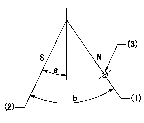
N:Pump normal
S:Stop the pump.
(1)Normal
(2)Pump speed aa and rack position bb (to be sealed at delivery)
(3)Use the hole above R = cc
----------
aa=0r/min bb=1-0.5mm cc=30mm
----------
a=32deg+-5deg b=70deg+-5deg
----------
aa=0r/min bb=1-0.5mm cc=30mm
----------
a=32deg+-5deg b=70deg+-5deg
0000001501 TAMPER PROOF

Tamperproofing-equipped boost compensator cover installation procedure
(A) After adjusting the boost compensator, tighten the bolts to remove the heads.
(1)Before adjusting the governor and the boost compensator, tighten the screw to the specified torque.
(Tightening torque T = T1 maximum)
(2)After adjusting the governor and the boost compensator, tighten to the specified torque to break off the bolt heads.
(Tightening torque T = T2 maximum)
----------
T1=2.5N-m(0.25kgf-m) T2=2.9~4.4N-m(0.3~0.45kgf-m)
----------
----------
T1=2.5N-m(0.25kgf-m) T2=2.9~4.4N-m(0.3~0.45kgf-m)
----------
Timing setting

(1)Pump vertical direction
(2)Coupling's key groove position at No 1 cylinder's beginning of injection
(3)-
(4)-
----------
----------
a=(70deg)
----------
----------
a=(70deg)
Information:
Cat does not warrant the quality or performance of non-Cat fluids.
Do NOT mix brands or types of SCA. Do NOT mix SCAs and extenders.Failure to follow the recommendations can result in shortened cooling system component life.
Use Only Approved SCAs. Conventional coolants require the maintenance addition of SCA throughout their expected life. Do NOT use an SCA with a coolant unless specifically approved by the coolant supplier for use with their coolant. It is the responsibility of the coolant manufacturer to ensure compatibility and acceptable performance.Failure to follow the recommendations can result in shortened cooling system component life.
Follow the maintenance information provided in the “Coolant and General Maintenance Recommendations” section in this Special Publication.Select a commercial diesel engine antifreeze coolant that meets all the requirements given in Table 1. The table contains the requirements for coolant to meet the published service intervals.The provided requirements are applicable to finished coolants and not for the concentrates. When concentrated coolant/antifreeze is mixed, Cat recommends mixing the concentrate with distilled water or with deionized water. If distilled water or deionized water is not available, water which has the required properties may be used. For the water properties, refer to this Special Publication, "General Coolant Information" article.Coolant/antifreezes for heavy-duty applications that meet "ASTM D6210" do not require treatment with SCA at the initial fill. Use the recommended 1:1 or higher concentration with recommended water. Treatment with SCA is required on a maintenance basis.The SCA manufacturer is responsible for ensuring the SCA is compatible with water meeting the “Caterpillar Minimum Acceptable Water Quality Requirements” as found in this Special Publication, and "ASTM D6210-08, Table X1.1". The coolant manufacturer and the SCA manufacturer are responsible to ensure that the products will not cause cooling system harm.Do not mix brands or types of coolants with different brands or types of SCA or extender.If using non Cat coolants, refer to the coolant manufacturer for information on a compatible SCA.Treat the compatible commercial coolant with 3 to 6 percent Cat SCA by volume. Maintain a 3 to 6 percent concentration level of SCA in the cooling system. For more information, refer to this Special Publication, "Conventional Coolant/Antifreeze Cooling System Maintenance" article.
Table 1
Technical Requirements for Commercial Diesel Engine Antifreeze Coolants
Specifications ASTM D6210-08
Additional Requirements Silicon: 100 ppm minimum to 275 ppm maximum
Nitrites: maintained at 1200ppm (70 grains/US gal) minimum to 2400 ppm (140 grains/US gal) maximum
Cat SCA at 3 to 6 percent (if Cat SCA is added)
Maintenance ASTM D6210-08 Add compatible SCA at maintenance intervals
Clean and flush the cooling system at drain intervals
Have questions with 106675-4591?
Group cross 106675-4591 ZEXEL
Komatsu
Komatsu
Dpico
Komatsu
Komatsu
Komatsu
Komatsu
Komatsu
Daewoo
106675-4591
9 400 617 406
INJECTION-PUMP ASSEMBLY
DE12TI
DE12TI