Information injection-pump assembly
ZEXEL
106675-4530
1066754530
Rating:
Cross reference number
ZEXEL
106675-4530
1066754530
Zexel num
Bosch num
Firm num
Name
106675-4530
INJECTION-PUMP ASSEMBLY
S6D140
S6D140
Calibration Data:
Adjustment conditions
Test oil
1404 Test oil ISO4113 or {SAEJ967d}
1404 Test oil ISO4113 or {SAEJ967d}
Test oil temperature
degC
40
40
45
Nozzle and nozzle holder
105780-8130
Bosch type code
EFEP215A
Nozzle
105780-0050
Bosch type code
DN6TD119NP1T
Nozzle holder
105780-2090
Bosch type code
EFEP215
Opening pressure
MPa
17.2
Opening pressure
kgf/cm2
175
Injection pipe
Outer diameter - inner diameter - length (mm) mm 8-3-600
Outer diameter - inner diameter - length (mm) mm 8-3-600
Overflow valve
131424-3420
Overflow valve opening pressure
kPa
255
221
289
Overflow valve opening pressure
kgf/cm2
2.6
2.25
2.95
Tester oil delivery pressure
kPa
157
157
157
Tester oil delivery pressure
kgf/cm2
1.6
1.6
1.6
RED3 control unit part number
407910-3
960
RED3 rack sensor specifications
mm
19
Direction of rotation (viewed from drive side)
Right R
Right R
Injection timing adjustment
Direction of rotation (viewed from drive side)
Right R
Right R
Injection order
1-5-3-6-
2-4
Pre-stroke
mm
3.9
3.85
3.95
Beginning of injection position
Drive side NO.1
Drive side NO.1
Difference between angles 1
Cal 1-5 deg. 60 59.5 60.5
Cal 1-5 deg. 60 59.5 60.5
Difference between angles 2
Cal 1-3 deg. 120 119.5 120.5
Cal 1-3 deg. 120 119.5 120.5
Difference between angles 3
Cal 1-6 deg. 180 179.5 180.5
Cal 1-6 deg. 180 179.5 180.5
Difference between angles 4
Cyl.1-2 deg. 240 239.5 240.5
Cyl.1-2 deg. 240 239.5 240.5
Difference between angles 5
Cal 1-4 deg. 300 299.5 300.5
Cal 1-4 deg. 300 299.5 300.5
Injection quantity adjustment
Rack position
(13.5)
Vist
V
1.82
1.82
1.82
Pump speed
r/min
900
900
900
Average injection quantity
mm3/st.
326
322
330
Max. variation between cylinders
%
0
-3
3
Basic
*
Injection quantity adjustment_02
Rack position
(6.9)
Vist
V
2.8
2.7
2.9
Pump speed
r/min
410
410
410
Average injection quantity
mm3/st.
17
15.5
18.5
Max. variation between cylinders
%
0
-15
15
Test data Ex:
Speed control lever angle

N:Pump normal
S:Stop the pump.
(1)Rack position = aa
(2)Rack position bb
----------
aa=20mm bb=1mm
----------
a=27deg+-5deg b=37deg+-5deg
----------
aa=20mm bb=1mm
----------
a=27deg+-5deg b=37deg+-5deg
0000000901
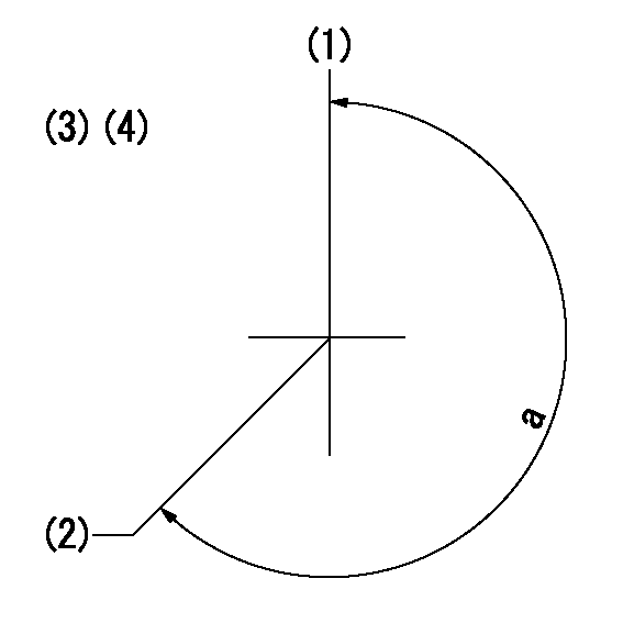
(1)Pump vertical direction
(2)Coupling's key groove position at No 1 cylinder's beginning of injection
(3)-
(4)-
----------
----------
a=(260deg)
----------
----------
a=(260deg)
Stop lever angle

(Rs) rack sensor specifications
(C/U) control unit part number
(V) Rack sensor output voltage
(R) Rack position (mm)
1. Confirming governor output characteristics (rack 19 mm, span 6 mm)
(1)When the output voltages of the rack sensor are V1 and V2, check that the rack positions R1 and R2 in the table above are satisfied.
----------
----------
----------
----------
Information:
Do not use the same vacuum sampling pump for extracting oil samples that is used for extracting coolant samples.A small residue of either type sample may remain in the pump and may cause a false positive analysis for the sample being taken.Always use a separate pump for oil sampling and a separate pump for coolant sampling.Failure to do so may cause a false analysis which could lead to customer and dealer concerns.
New Systems, Refilled Systems, and Converted Systems
Perform an S O S coolant analysis (Level 2) at the following maintenance intervals.
Initial 500 service hours
Every Year or every 2000 hours, whichever comes firstPerform this analysis at the interval that occurs first for new systems, for refilled systems, or for converted systems that use Cat ELC (Extended Life Coolant) or use Cat DEAC (Diesel Engine Antifreeze/Coolant). This 500 hour check will also check for any residual cleaner that may have contaminated the system.Recommended Interval for S O S Services Coolant Sample
The following table contains the recommended sampling interval for all coolants that meet Cat EC-1 (Engine Coolant specification - 1). This is also the recommended sampling interval for all conventional heavy-duty coolant/antifreeze.The Level 2 Coolant Analysis should be performed if a problem is suspected or identified.
Table 1
Recommended Interval
Type of Coolant Level 1 Level 2
Cat DEAC
and Conventional Heavy-Duty Coolants Every 250 hours Yearly
Cat ELC
and Commercial EC-1 coolants Optional or every 500 hours Yearly or every 500 hours Note: Check the SCA (Supplemental Coolant Additive) of the conventional coolant at every oil change or at every 250 hours. Perform this check at the interval that occurs first.Refer to your machine OMM for recommendations specific to your machine.S O S Services Coolant Analysis (Level 1)
A coolant analysis (Level 1) is a test of the properties of the coolant.The following properties of the coolant are tested:
Glycol concentration for freeze protection and boil protection
Ability to protect from erosion and corrosion
pH
Conductivity
Visual analysis
Odor analysisThe results are reported, and appropriate recommendations are made.S O S Services Coolant Analysis (Level 2)
A coolant analysis ( Level 2) is a comprehensive chemical evaluation of the coolant. This analysis is also a check of the overall condition of the cooling system.The S O S coolant analysis ( Level 2) has the following features:
Full coolant analysis (Level 1)
Identification of metal corrosion and of contaminants
Identification of buildup of the impurities that cause corrosion
Identification of buildup of the impurities that cause scaling
Determination of the possibility of electrolysis within the cooling system of the engineThe results are reported, and appropriate recommendations are made.For more information on S O S coolant analysis, consult your Caterpillar dealer.
Have questions with 106675-4530?
Group cross 106675-4530 ZEXEL
Komatsu
Komatsu
Dpico
106675-4530
INJECTION-PUMP ASSEMBLY
S6D140
S6D140