Information injection-pump assembly
ZEXEL
106675-4450
1066754450

Rating:
Cross reference number
ZEXEL
106675-4450
1066754450
Zexel num
Bosch num
Firm num
Name
Calibration Data:
Adjustment conditions
Test oil
1404 Test oil ISO4113 or {SAEJ967d}
1404 Test oil ISO4113 or {SAEJ967d}
Test oil temperature
degC
40
40
45
Nozzle and nozzle holder
105780-8140
Bosch type code
EF8511/9A
Nozzle
105780-0000
Bosch type code
DN12SD12T
Nozzle holder
105780-2080
Bosch type code
EF8511/9
Opening pressure
MPa
17.2
Opening pressure
kgf/cm2
175
Injection pipe
Outer diameter - inner diameter - length (mm) mm 8-3-600
Outer diameter - inner diameter - length (mm) mm 8-3-600
Overflow valve
131424-4420
Overflow valve opening pressure
kPa
157
123
191
Overflow valve opening pressure
kgf/cm2
1.6
1.25
1.95
Tester oil delivery pressure
kPa
157
157
157
Tester oil delivery pressure
kgf/cm2
1.6
1.6
1.6
Direction of rotation (viewed from drive side)
Right R
Right R
Injection timing adjustment
Direction of rotation (viewed from drive side)
Right R
Right R
Injection order
1-5-3-6-
2-4
Pre-stroke
mm
4.3
4.25
4.35
Beginning of injection position
Governor side NO.1
Governor side NO.1
Difference between angles 1
Cal 1-5 deg. 60 59.5 60.5
Cal 1-5 deg. 60 59.5 60.5
Difference between angles 2
Cal 1-3 deg. 120 119.5 120.5
Cal 1-3 deg. 120 119.5 120.5
Difference between angles 3
Cal 1-6 deg. 180 179.5 180.5
Cal 1-6 deg. 180 179.5 180.5
Difference between angles 4
Cyl.1-2 deg. 240 239.5 240.5
Cyl.1-2 deg. 240 239.5 240.5
Difference between angles 5
Cal 1-4 deg. 300 299.5 300.5
Cal 1-4 deg. 300 299.5 300.5
Injection quantity adjustment
Adjusting point
A
Rack position
10.8
Pump speed
r/min
1100
1100
1100
Average injection quantity
mm3/st.
150.6
148.6
152.6
Max. variation between cylinders
%
0
-2
2
Basic
*
Fixing the lever
*
Boost pressure
kPa
80
80
Boost pressure
mmHg
600
600
Injection quantity adjustment_02
Adjusting point
B
Rack position
4.9+-0.5
Pump speed
r/min
400
400
400
Average injection quantity
mm3/st.
15.5
14
17
Max. variation between cylinders
%
0
-15
15
Fixing the rack
*
Boost pressure
kPa
0
0
0
Boost pressure
mmHg
0
0
0
Injection quantity adjustment_03
Adjusting point
E
Rack position
-
Pump speed
r/min
100
100
100
Average injection quantity
mm3/st.
146
146
156
Fixing the lever
*
Boost pressure
kPa
0
0
0
Boost pressure
mmHg
0
0
0
Rack limit
*
Boost compensator adjustment
Pump speed
r/min
500
500
500
Rack position
R1-0.65
Boost pressure
kPa
13.3
11.3
15.3
Boost pressure
mmHg
100
85
115
Boost compensator adjustment_02
Pump speed
r/min
500
500
500
Rack position
R1(10.8)
Boost pressure
kPa
66.7
66.7
66.7
Boost pressure
mmHg
500
500
500
Test data Ex:
Governor adjustment

N:Pump speed
R:Rack position (mm)
(1)Target notch: K
(2)Tolerance for racks not indicated: +-0.05mm.
(3)Deliver without the torque control spring operating.
(4)RACK LIMIT
(5)Boost compensator stroke: BCL
(6)Set idle sub-spring
----------
K=10 BCL=0.65+-0.1mm
----------
----------
K=10 BCL=0.65+-0.1mm
----------
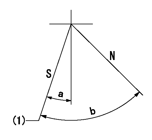
Speed control lever angle

F:Full speed
I:Idle
(1)Stopper bolt setting
----------
----------
a=10deg+-5deg b=26deg+-5deg
----------
----------
a=10deg+-5deg b=26deg+-5deg
Stop lever angle
N:Pump normal
S:Stop the pump.
(1)Pump speed aa and rack position bb (to be sealed at delivery)
----------
aa=0r/min bb=1-0.5mm
----------
a=25deg+-5deg b=70deg+-5deg
----------
aa=0r/min bb=1-0.5mm
----------
a=25deg+-5deg b=70deg+-5deg
Timing setting

(1)Pump vertical direction
(2)Coupling's key groove position at No 1 cylinder's beginning of injection
(3)-
(4)-
----------
----------
a=(70deg)
----------
----------
a=(70deg)
Information:
The DATA SET screen ID (2) for the correct group will be listed to the right of Line 011 FUEL INJECT PUMP BENCH TEST SPEC NUM (3). Write this number DMXXXX-XX down and proceed to Section ""Displaying the DATA SET Screen When the DATA SET ID Number is Not Known"".Certain pump and governor groups will have multiple DATA SETS. Change in pump design will be tracked by pump serial number. Figure 22 is an example of a serial l number break in the data (1). The original DATA SET DMXXXX number is kept (2) but the new DATA SET has a different change level (3).
Illustration 22 g02797952
Note: Soon you will be able to use the tab key to place the cursor in front of this line. Type an X to select, Figure 21 (4). Press the enter key. The data will be displayed automatically. For now though the data will have to be displayed manually. Figure 23 (1)
Illustration 23 g02797956
Press the pf3 key to return to the ACF2 screen (2) .Proceed to Section ""Displaying the DATA SET Screen When the DATA SET ID Number is Not Known"".Displaying the DATA SET Screen When the DATA SET ID Number is Not Known
At the ACF2/IMS ONLINE MENU SYSTEM screen (1) (TMI 1.04) press the enter key (2). Figure 24
Illustration 24 g02797958
This will display the ACF2/IMS APPLICATION SELECTION MENU. Figure 25 (1) (TMI 1.05)
Illustration 25 g02797959
Use the tab key to place the cursor in front of the line GKN402 TMI - ENGINE AND COMP PERF, type an X to select (2) or type GKN402 at the APPLICATION SELECTION NO. _. (3) Press the enter key. This will display the ACF2/IMS PROGRAM SELECTION MENU screen. Figure 26 (1)
Illustration 26 g02797960
Use the tab key to place the cursor in front of line 03 and type an X to select (2) or type 03 at the PROGRAM SELECTION NO _ (3). Press the enter key. This will display the PERFORMANCE PARAMETERS INQUIRY screen. Figure 27 (1) (TMI 3.03 p1)
Illustration 27 g02797962
Type the appropriate numbers in the DATA REFERENCE NUMBER and CHANGE LEVEL fields (2). Press the enter key. The data set will be displayed on the next screen. Figure 28 (TMI 3.03)
Illustration 28 g02797963
Press the pf3 key to return to the ACF2 screen (1) .Interpreting the Specification Data Set Screens
The following screen contains flow specifications and physical parameters necessary to evaluate a fuel injection pump. Additional parameters such as calibration fluid temperatures and pressures are listed in the manual for the test bench. See Special Instruction, SEHS8200. These screens still apply to this data. Every data set (DMXXXX screen) contains data for many injection pump and governor group part numbers. The data is sorted by the profile or geometry of the basic cam and the lowest level part number of the plunger and barrel group. Most part numbers with the same basic cam, plunger, and barrel groups use the same data.Pages of data in the DATA SETS are arranged in descending pump rpm. Five or six rpm choices are listed. When the