Information injection-pump assembly
ZEXEL
106675-4330
1066754330
KOMATSU
6152721220
6152721220

Rating:
Cross reference number
ZEXEL
106675-4330
1066754330
KOMATSU
6152721220
6152721220
Zexel num
Bosch num
Firm num
Name
Calibration Data:
Adjustment conditions
Test oil
1404 Test oil ISO4113 or {SAEJ967d}
1404 Test oil ISO4113 or {SAEJ967d}
Test oil temperature
degC
40
40
45
Nozzle and nozzle holder
105780-8140
Bosch type code
EF8511/9A
Nozzle
105780-0000
Bosch type code
DN12SD12T
Nozzle holder
105780-2080
Bosch type code
EF8511/9
Opening pressure
MPa
17.2
Opening pressure
kgf/cm2
175
Injection pipe
Outer diameter - inner diameter - length (mm) mm 8-3-600
Outer diameter - inner diameter - length (mm) mm 8-3-600
Overflow valve
131424-1520
Overflow valve opening pressure
kPa
157
123
191
Overflow valve opening pressure
kgf/cm2
1.6
1.25
1.95
Tester oil delivery pressure
kPa
157
157
157
Tester oil delivery pressure
kgf/cm2
1.6
1.6
1.6
Direction of rotation (viewed from drive side)
Left L
Left L
Injection timing adjustment
Direction of rotation (viewed from drive side)
Left L
Left L
Injection order
1-5-3-6-
2-4
Pre-stroke
mm
3.8
3.75
3.85
Beginning of injection position
Drive side NO.1
Drive side NO.1
Difference between angles 1
Cal 1-5 deg. 60 59.5 60.5
Cal 1-5 deg. 60 59.5 60.5
Difference between angles 2
Cal 1-3 deg. 120 119.5 120.5
Cal 1-3 deg. 120 119.5 120.5
Difference between angles 3
Cal 1-6 deg. 180 179.5 180.5
Cal 1-6 deg. 180 179.5 180.5
Difference between angles 4
Cyl.1-2 deg. 240 239.5 240.5
Cyl.1-2 deg. 240 239.5 240.5
Difference between angles 5
Cal 1-4 deg. 300 299.5 300.5
Cal 1-4 deg. 300 299.5 300.5
Injection quantity adjustment
Adjusting point
A
Rack position
9.5
Pump speed
r/min
975
975
975
Average injection quantity
mm3/st.
177.5
173.5
181.5
Max. variation between cylinders
%
0
-3
3
Basic
*
Fixing the lever
*
Boost pressure
kPa
64
64
Boost pressure
mmHg
480
480
Injection quantity adjustment_02
Adjusting point
C
Rack position
5.7+-0.5
Pump speed
r/min
400
400
400
Average injection quantity
mm3/st.
11
9.5
12.5
Max. variation between cylinders
%
0
-15
15
Fixing the rack
*
Boost pressure
kPa
0
0
0
Boost pressure
mmHg
0
0
0
Injection quantity adjustment_03
Adjusting point
E
Rack position
10+0.2
Pump speed
r/min
100
100
100
Average injection quantity
mm3/st.
165
145
185
Fixing the lever
*
Boost pressure
kPa
0
0
0
Boost pressure
mmHg
0
0
0
Rack limit
*
Boost compensator adjustment
Pump speed
r/min
600
600
600
Rack position
R1-1.45
Boost pressure
kPa
14.7
12
17.4
Boost pressure
mmHg
110
90
130
Boost compensator adjustment_02
Pump speed
r/min
600
600
600
Rack position
R1(9.5)
Boost pressure
kPa
50.7
44
57.4
Boost pressure
mmHg
380
330
430
Test data Ex:
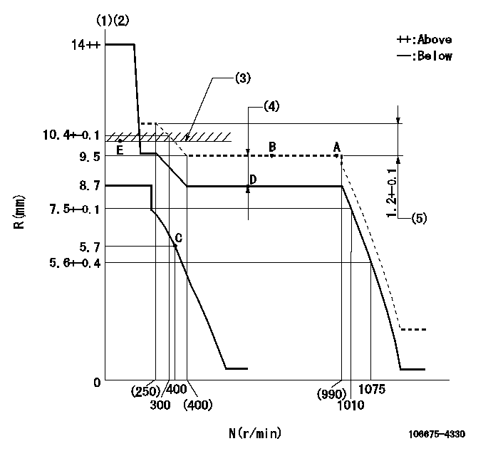
Governor adjustment

N:Pump speed
R:Rack position (mm)
(1)Target notch: K
(2)Tolerance for racks not indicated: +-0.05mm.
(3)RACK LIMIT: RAL
(4)Boost compensator stroke: BCL
(5)Rack difference between N = N1 and N = N2
----------
K=10 RAL=10+0.2mm BCL=1.45+-0.1mm N1=975r/min N2=230r/min
----------
----------
K=10 RAL=10+0.2mm BCL=1.45+-0.1mm N1=975r/min N2=230r/min
----------
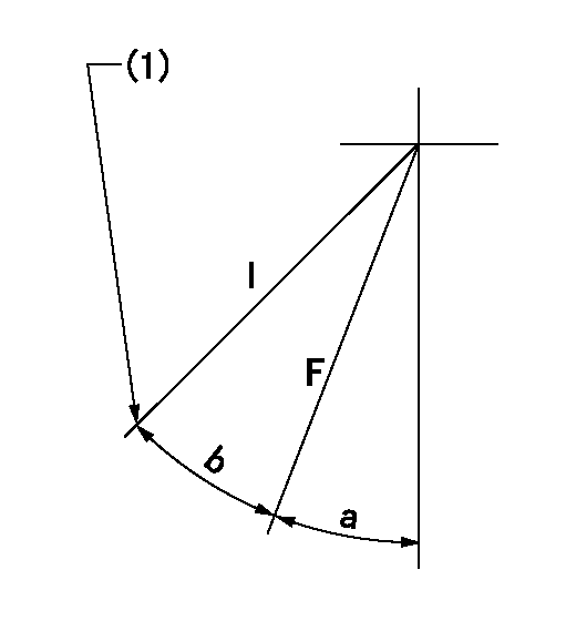
Speed control lever angle

F:Full speed
I:Idle
(1)Stopper bolt setting
----------
----------
a=3deg+-5deg b=20deg+-5deg
----------
----------
a=3deg+-5deg b=20deg+-5deg
Stop lever angle

N:Pump normal
S:Stop the pump.
(1)Rack position = aa, speed = bb (stamp at delivery)
----------
aa=1-0.5mm bb=0r/min
----------
a=33deg+-5deg b=70deg+-5deg
----------
aa=1-0.5mm bb=0r/min
----------
a=33deg+-5deg b=70deg+-5deg
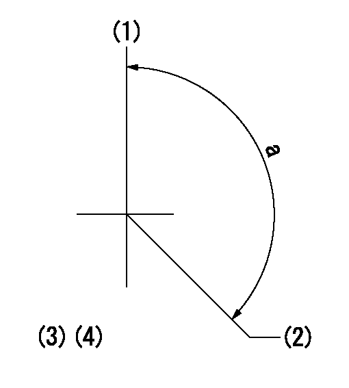
Timing setting

(1)Pump vertical direction
(2)Coupling's key groove position at No 1 cylinder's beginning of injection
(3)-
(4)-
----------
----------
a=(150deg)
----------
----------
a=(150deg)
Information:
Parts Location
Illustration 2 g01601433
(1) 308-4943 Diesel Particulate Filter Group (2) 235-3963 Clamp Assembly (3) 308-4945 Bracket Assembly (4) 8T-4183 Bolt (5) 5P-8245 Hard Washer (6) 241-9265 Muffler Clamp Installation Procedure
Diesel Particulate Filter Installation
Illustration 3 g01606937
Typical Example (11) Existing muffler assembly (12) Existing bracket assembly (13) Support Assembly (14) Muffler Clamp (15) Tube assembly (16) Engine lifting plate (17) Bolt (18) Hard washer (19) Bolt
Remove existing muffler assembly (11) and bracket assembly (12). Set aside the three 8T-4183 Bolts (17), the five 8T-4184 Bolts (19) and the eight 5P-1076 Hard Washers (18). These parts will be reused in Steps 2 and 3. Refer to Illustration 3.
Illustration 4 g01601354
(3) 308-4945 Bracket Assembly (17) Bolt (18) Hard washer
Install 308-4945 Bracket Assembly (3) onto support assembly (13) by reusing three bolts (17) and three hard washers (18) that were removed in Step 1. Refer to Illustrations 3 and 4.
Illustration 5 g01601373
(19) Bolt
Reuse five bolts (19) and five hard washers (18) removed in Step 1 to secure bracket assembly (3) to engine lifting plate (16). Refer to Illustrations 3 and 5.
Illustration 6 g01601413
(2) 235-3963 Clamp Assembly (Lower half) (4) 8T-4183 Bolt (5) 5P-8245 Hard Washer
Remove the two bolts, two hard washers, two lock washers, and two nuts from each 235-3963 Clamp Assembly (2). Keep these parts together with the upper half of clamp assembly (2). These parts will be reinstalled in Step 8.
Install the lower half of 235-3963 Clamp Assembly (2) by using two 8T-4183 Bolts (4) and two 5P-8245 Hard Washers (5). Loosely secure these bolts so that the clamp assembly is adjustable. Repeat for the other clamp assembly (2). Refer to Illustration 6.
Illustration 7 g01601473
(1) 308-4943 Diesel Particulate Filter Gp
Install 308-4943 Diesel Particulate Filter Group (1) onto the lower halves of clamp assemblies (2). The weight of the diesel particulate filter group is approximately 40 kg (88 lb). Make sure that the inlet tube (not shown) of the inlet module of the diesel particulate filter fits into tube assembly (15). Use a new 241-9265 Muffler Clamp (6) to secure the connection. Refer to Illustrations 3 and 7.
Illustration 8 g01601333
(2) 235-3963 Clamp Assembly (Upper half) (2a) Bolt (2b) Hard washer (2c) Lock washer (2d) Nut
Once you have properly installed the tube assembly, tighten both bolts (4) to secure the bottom half of clamp assembly (2). Repeat for the other clamp assembly (4). Install the upper half of clamp assembly (2) by using two bolts (2a) and two hard washers (2b) through the upper clamp assembly, and two lock washers (2c) and two nuts (2d) on the lower clamp assembly. Repeat for the other clamp assembly. Refer to Illustration 8.
Reconnect the drain lines.Exhaust Monitor Installation
Refer to Special Instruction, REHS5606, "Installation and Operation of the Exhaust Monitor Used in All Diesel Particulate Filter (DPF) Retrofit Emissions Applications" for information regarding the installation and the operation of the exhaust monitor.The exhaust