Information injection-pump assembly
ZEXEL
106675-4241
1066754241
Rating:
Service parts 106675-4241 INJECTION-PUMP ASSEMBLY:
1.
_
5.
AUTOM. ADVANCE MECHANIS
6.
COUPLING PLATE
7.
COUPLING PLATE
8.
_
9.
_
11.
Nozzle and Holder
12.
Open Pre:MPa(Kqf/cm2)
22.6{230}

15.
NOZZLE SET
Include in #1:
106675-4241
as INJECTION-PUMP ASSEMBLY
Cross reference number
ZEXEL
106675-4241
1066754241
Zexel num
Bosch num
Firm num
Name
106675-4241
INJECTION-PUMP ASSEMBLY
Calibration Data:
Adjustment conditions
Test oil
1404 Test oil ISO4113 or {SAEJ967d}
1404 Test oil ISO4113 or {SAEJ967d}
Test oil temperature
degC
40
40
45
Nozzle and nozzle holder
105780-8140
Bosch type code
EF8511/9A
Nozzle
105780-0000
Bosch type code
DN12SD12T
Nozzle holder
105780-2080
Bosch type code
EF8511/9
Opening pressure
MPa
17.2
Opening pressure
kgf/cm2
175
Injection pipe
Outer diameter - inner diameter - length (mm) mm 8-3-600
Outer diameter - inner diameter - length (mm) mm 8-3-600
Overflow valve
131424-1520
Overflow valve opening pressure
kPa
157
123
191
Overflow valve opening pressure
kgf/cm2
1.6
1.25
1.95
Tester oil delivery pressure
kPa
157
157
157
Tester oil delivery pressure
kgf/cm2
1.6
1.6
1.6
Direction of rotation (viewed from drive side)
Right R
Right R
Injection timing adjustment
Direction of rotation (viewed from drive side)
Right R
Right R
Injection order
1-4-2-6-
3-5
Pre-stroke
mm
3.3
3.25
3.35
Beginning of injection position
Drive side NO.1
Drive side NO.1
Difference between angles 1
Cal 1-4 deg. 60 59.5 60.5
Cal 1-4 deg. 60 59.5 60.5
Difference between angles 2
Cyl.1-2 deg. 120 119.5 120.5
Cyl.1-2 deg. 120 119.5 120.5
Difference between angles 3
Cal 1-6 deg. 180 179.5 180.5
Cal 1-6 deg. 180 179.5 180.5
Difference between angles 4
Cal 1-3 deg. 240 239.5 240.5
Cal 1-3 deg. 240 239.5 240.5
Difference between angles 5
Cal 1-5 deg. 300 299.5 300.5
Cal 1-5 deg. 300 299.5 300.5
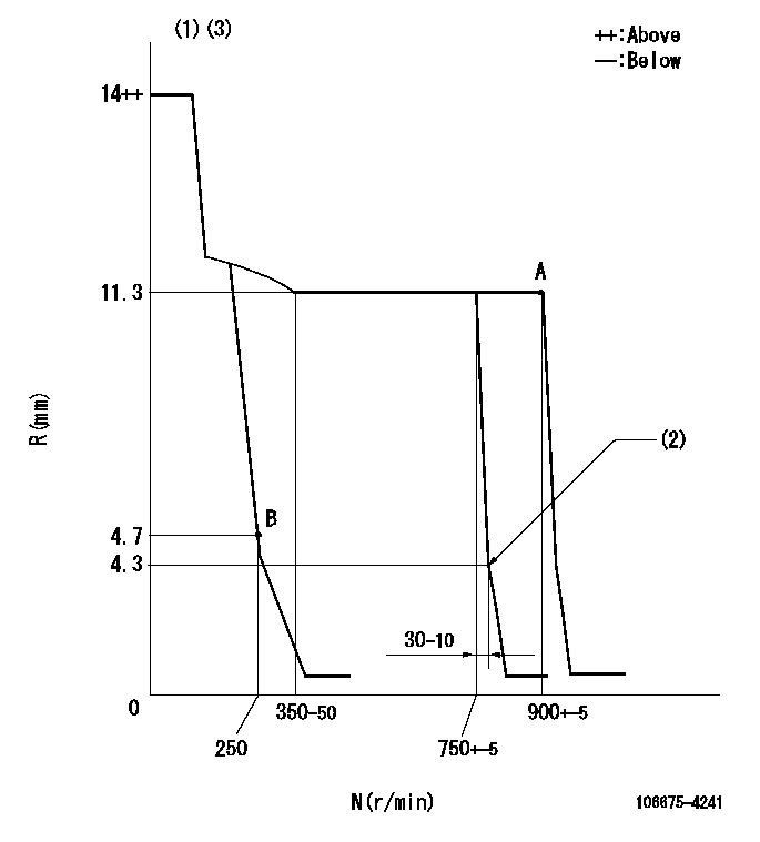
Injection quantity adjustment
Adjusting point
A
Rack position
11.3
Pump speed
r/min
900
900
900
Each cylinder's injection qty
mm3/st.
150.6
148
153.2
Basic
*
Fixing the rack
*
Injection quantity adjustment_02
Adjusting point
B
Rack position
4.7+-0.5
Pump speed
r/min
250
250
250
Each cylinder's injection qty
mm3/st.
24
21.6
26.4
Fixing the rack
*
Test data Ex:
Governor adjustment
N:Pump speed
R:Rack position (mm)
(1)Target notch: K
(2)Idle sub spring setting: L1.
(3)Confirm that the rack is pulled back to R = R1 or less at solenoid operation (N = 0).
----------
K=13 L1=4.3-0.5mm R1=4.2mm
----------
----------
K=13 L1=4.3-0.5mm R1=4.2mm
----------
Speed control lever angle
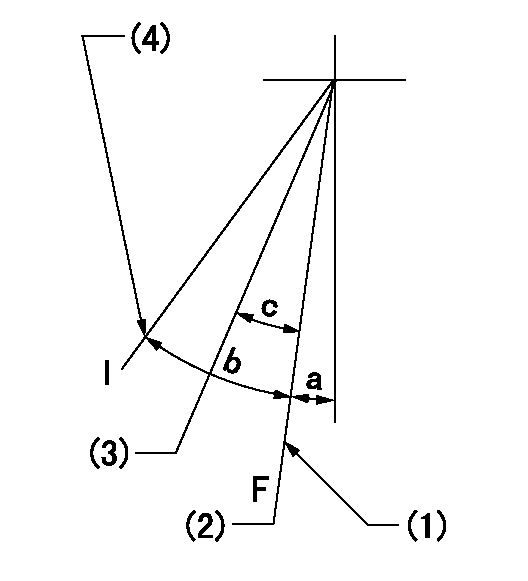
F:Full speed
I:Idle
(1)Stopper bolt setting
(2)Set the pump speed at aa
(3)Set the pump speed at bb.
(4)Stopper bolt setting
----------
aa=900r/min bb=750r/min
----------
a=21deg+-5deg b=28deg+-5deg c=6deg+-5deg
----------
aa=900r/min bb=750r/min
----------
a=21deg+-5deg b=28deg+-5deg c=6deg+-5deg
Stop lever angle
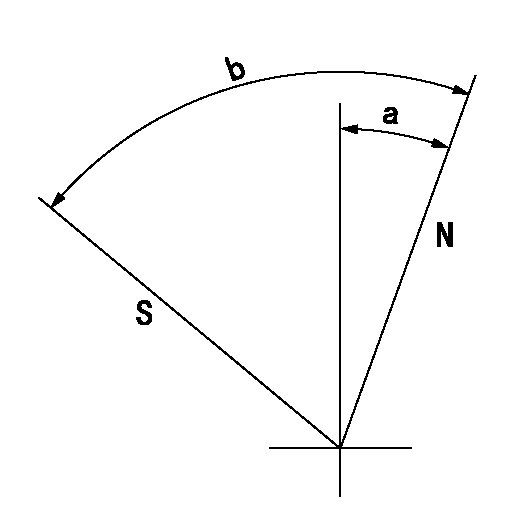
N:Pump normal
S:Stop the pump.
----------
----------
a=20deg+-5deg b=53deg+-5deg
----------
----------
a=20deg+-5deg b=53deg+-5deg
Timing setting

(1)Pump vertical direction
(2)Position of camshaft's key groove at No 1 cylinder's beginning of injection
(3)-
(4)-
----------
----------
a=(50deg)
----------
----------
a=(50deg)
Information:
Illustration 1 g00564916The test for the engine oil pressure switch is a test for the actuation of the engine oil pressure and a test for the electrical continuity. This test will determine if the engine oil pressure switch is faulty and if the engine oil pressure switch needs to be replaced. Use the 1U-5470 Engine Pressure Group and the 8T-0500 Continuity Tester for this test.
If an access hole that has the same engine oil pressure as the engine oil pressure switch is not close to the engine oil pressure switch, remove the engine oil pressure switch. Install a tee at this location. Install the engine oil pressure switch on one side of the tee, and connect the 1U-5470 Engine Pressure Group on the opposite side of the tee. Note: This test can also be performed on a bench with air pressure if the correct fittings are available.
Disconnect the connector for the engine oil pressure switch from the junction box. While the engine is stopped, check the continuity between contact (2) and common contact (1). The continuity should be open. Next, check the continuity between contact (3) and common contact (1). This continuity should be closed.
Start the engine and allow the engine to run. Observe the 8T-0500 Continuity Tester and the 1U-5470 Engine Pressure Group from the time that the engine is started until the engine is running. The continuity between contact (2) and common contact (1) should close when the engine oil pressure is greater than the deactuation pressure of the engine oil pressure switch. The engine should begin to run and the starting motor should disengage when the engine oil pressure is above the deactuation pressure of the engine oil pressure switch. Record the reading from the pressure gauge when the continuity of the engine oil pressure switch changes. Compare the reading with the specifications for the deactuation pressure of the engine oil pressure switch.
The engine oil pressure switch should close across contact (2) and common contact (1) when the engine oil pressure is above the specified deactuation pressure of the engine oil pressure switch. If the engine oil pressure switch does not close the engine oil pressure switch is faulty. Replace the faulty switch.
Have questions with 106675-4241?
Group cross 106675-4241 ZEXEL
Yanmar
106675-4241
INJECTION-PUMP ASSEMBLY