Information injection-pump assembly
ZEXEL
106675-4231
1066754231
Rating:
Service parts 106675-4231 INJECTION-PUMP ASSEMBLY:
1.
_
5.
AUTOM. ADVANCE MECHANIS
6.
COUPLING PLATE
7.
COUPLING PLATE
8.
_
9.
_
11.
Nozzle and Holder
12.
Open Pre:MPa(Kqf/cm2)
22.6{230}

15.
NOZZLE SET
Include in #1:
106675-4231
as INJECTION-PUMP ASSEMBLY
Cross reference number
ZEXEL
106675-4231
1066754231
Zexel num
Bosch num
Firm num
Name
106675-4231
INJECTION-PUMP ASSEMBLY
Calibration Data:
Adjustment conditions
Test oil
1404 Test oil ISO4113 or {SAEJ967d}
1404 Test oil ISO4113 or {SAEJ967d}
Test oil temperature
degC
40
40
45
Nozzle and nozzle holder
105780-8140
Bosch type code
EF8511/9A
Nozzle
105780-0000
Bosch type code
DN12SD12T
Nozzle holder
105780-2080
Bosch type code
EF8511/9
Opening pressure
MPa
17.2
Opening pressure
kgf/cm2
175
Injection pipe
Outer diameter - inner diameter - length (mm) mm 8-3-600
Outer diameter - inner diameter - length (mm) mm 8-3-600
Overflow valve
131424-1520
Overflow valve opening pressure
kPa
157
123
191
Overflow valve opening pressure
kgf/cm2
1.6
1.25
1.95
Tester oil delivery pressure
kPa
157
157
157
Tester oil delivery pressure
kgf/cm2
1.6
1.6
1.6
Direction of rotation (viewed from drive side)
Right R
Right R
Injection timing adjustment
Direction of rotation (viewed from drive side)
Right R
Right R
Injection order
1-4-2-6-
3-5
Pre-stroke
mm
3.3
3.25
3.35
Beginning of injection position
Drive side NO.1
Drive side NO.1
Difference between angles 1
Cal 1-4 deg. 60 59.5 60.5
Cal 1-4 deg. 60 59.5 60.5
Difference between angles 2
Cyl.1-2 deg. 120 119.5 120.5
Cyl.1-2 deg. 120 119.5 120.5
Difference between angles 3
Cal 1-6 deg. 180 179.5 180.5
Cal 1-6 deg. 180 179.5 180.5
Difference between angles 4
Cal 1-3 deg. 240 239.5 240.5
Cal 1-3 deg. 240 239.5 240.5
Difference between angles 5
Cal 1-5 deg. 300 299.5 300.5
Cal 1-5 deg. 300 299.5 300.5
Injection quantity adjustment
Adjusting point
A
Rack position
11.3
Pump speed
r/min
900
900
900
Each cylinder's injection qty
mm3/st.
150.6
148
153.2
Basic
*
Fixing the rack
*
Injection quantity adjustment_02
Adjusting point
B
Rack position
4.7+-0.5
Pump speed
r/min
250
250
250
Each cylinder's injection qty
mm3/st.
24
21.6
26.4
Fixing the rack
*
Test data Ex:
Governor adjustment
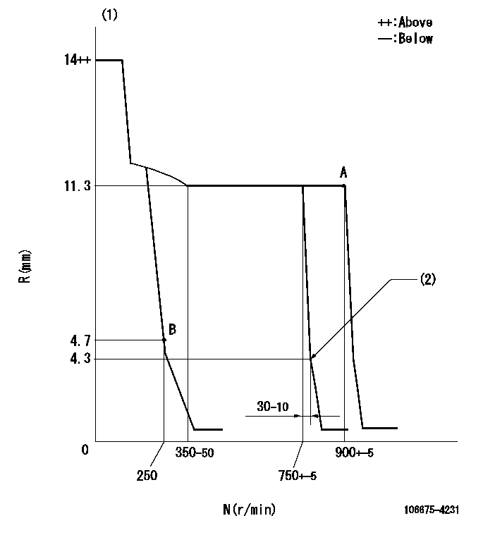
N:Pump speed
R:Rack position (mm)
(1)Target notch: K
(2)Idle sub spring setting: L1.
----------
K=13 L1=4.3-0.5mm
----------
----------
K=13 L1=4.3-0.5mm
----------
Speed control lever angle
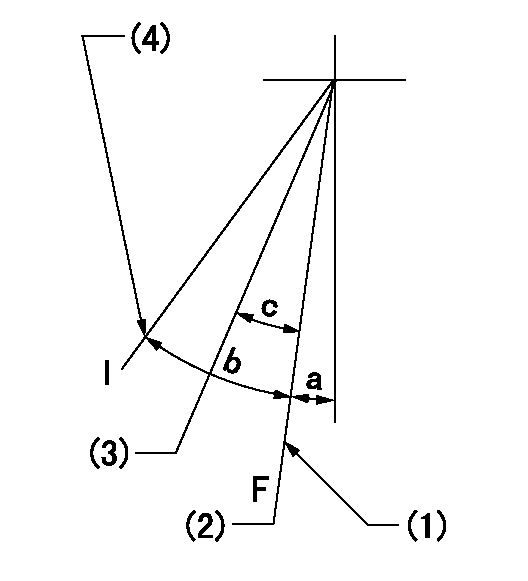
F:Full speed
I:Idle
(1)Stopper bolt setting
(2)Set the pump speed at aa
(3)Set the pump speed at bb.
(4)Stopper bolt setting
----------
aa=900r/min bb=750r/min
----------
a=21deg+-5deg b=28deg+-5deg c=6deg+-5deg
----------
aa=900r/min bb=750r/min
----------
a=21deg+-5deg b=28deg+-5deg c=6deg+-5deg
Stop lever angle
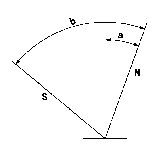
N:Pump normal
S:Stop the pump.
----------
----------
a=20deg+-5deg b=53deg+-5deg
----------
----------
a=20deg+-5deg b=53deg+-5deg
Timing setting

(1)Pump vertical direction
(2)Position of camshaft's key groove at No 1 cylinder's beginning of injection
(3)-
(4)-
----------
----------
a=(50deg)
----------
----------
a=(50deg)
Information:
Illustration 1 g00564355
7W-2743 Electronic Speed Switch (ESS)
(1) Push button for Overspeed Verification
(2) Reset button
(3) Overspeed indicator lamp
(4) Seal screw plug for adjusting the engine overspeed
(5) Seal screw plug for adjusting the crank terminate speed
(6) Seal screw plug for adjusting the oil step pressure speed setting The calibration of the crank terminate adjustment can increase the crank terminate speed or the calibration of the crank terminate adjustment can decrease the crank terminate speed. The crank terminate speed determines when the starting motor is disengaged. The starting motor is disengaged when the system voltage is cancelled by the crank termination speed. At the crank terminate speed, the engine must be able to run without the assistance of the starting motor.
Remove the lockwire and the seal from seal screw plug (5). Remove seal screw plug (5) from the access hole for the crank terminate adjusting screw.
Use a small screwdriver to lightly turn the crank terminate adjusting screw in the direction of the "MAX" arrow or the clockwise direction. Turn the screw twenty times. The crank terminate adjusting screw will vary the setting of a potentiometer that is inside of the ESS. The crank terminate adjusting screw will not cause damage to the potentiometer. Also, the screw can not be removed if the screw is turned in the wrong direction.
Turn the crank terminate adjusting screw for twelve turns in the opposite direction of the "MAX" arrow or the counterclockwise direction. This will establish an approximate crank terminate setting.
Connect a voltmeter with the positive lead at terminal (ESS-12) and the negative lead at (ESS-5). Use a 6V-7070 Digital Multimeter or a voltmeter with the same accuracy. Start the engine. Record the engine rpm when the starting motor disengages. The starting motor disengages when the open circuit voltage is cancelled by the crank terminate setting. Refer to the Speed Specification Chart for the correct crank terminate setting.
If the setting in Step 4 is not correct, proceed with Steps 6, 7, and 8. If the setting is correct go to Step 8.
Stop the engine and turn the crank terminate adjusting screw for one full turn in the clockwise direction in order to increase the crank terminate speed. Turn the crank terminate adjusting screw for one full turn in the counterclockwise direction in order to decrease the crank terminate speed.
While the voltmeter is still connected, start the engine. Record the engine rpm when the starting motor disengages. The starting motor will disengage when the voltage is cancelled by the crank terminate speed. Repeat Steps 6 and 7 until the crank terminate speed is correct.
Install seal screw plug (5) in the access hole for the crank terminate adjusting screw. Tighten the screw to a torque of 0.20 0.03 N m (1.8 .3 lb in). Install the lockwire and the seal if the overspeed calibration and the oil step speed calibration are also complete.
Have questions with 106675-4231?
Group cross 106675-4231 ZEXEL
Komatsu
106675-4231
INJECTION-PUMP ASSEMBLY