Information injection-pump assembly
BOSCH
9 400 617 385
9400617385
ZEXEL
106675-4221
1066754221
KOMATSU
6211711681
6211711681
Rating:
Cross reference number
BOSCH
9 400 617 385
9400617385
ZEXEL
106675-4221
1066754221
KOMATSU
6211711681
6211711681
Zexel num
Bosch num
Firm num
Name
106675-4221
9 400 617 385
6211711681 KOMATSU
INJECTION-PUMP ASSEMBLY
S6D140 K
S6D140 K
Calibration Data:
Adjustment conditions
Test oil
1404 Test oil ISO4113 or {SAEJ967d}
1404 Test oil ISO4113 or {SAEJ967d}
Test oil temperature
degC
40
40
45
Nozzle and nozzle holder
105780-8140
Bosch type code
EF8511/9A
Nozzle
105780-0000
Bosch type code
DN12SD12T
Nozzle holder
105780-2080
Bosch type code
EF8511/9
Opening pressure
MPa
17.2
Opening pressure
kgf/cm2
175
Injection pipe
Outer diameter - inner diameter - length (mm) mm 8-3-600
Outer diameter - inner diameter - length (mm) mm 8-3-600
Overflow valve
131425-1620
Overflow valve opening pressure
kPa
255
221
289
Overflow valve opening pressure
kgf/cm2
2.6
2.25
2.95
Tester oil delivery pressure
kPa
157
157
157
Tester oil delivery pressure
kgf/cm2
1.6
1.6
1.6
Direction of rotation (viewed from drive side)
Right R
Right R
Injection timing adjustment
Direction of rotation (viewed from drive side)
Right R
Right R
Injection order
1-5-3-6-
2-4
Pre-stroke
mm
4.3
4.25
4.35
Beginning of injection position
Drive side NO.1
Drive side NO.1
Difference between angles 1
Cal 1-5 deg. 60 59.5 60.5
Cal 1-5 deg. 60 59.5 60.5
Difference between angles 2
Cal 1-3 deg. 120 119.5 120.5
Cal 1-3 deg. 120 119.5 120.5
Difference between angles 3
Cal 1-6 deg. 180 179.5 180.5
Cal 1-6 deg. 180 179.5 180.5
Difference between angles 4
Cyl.1-2 deg. 240 239.5 240.5
Cyl.1-2 deg. 240 239.5 240.5
Difference between angles 5
Cal 1-4 deg. 300 299.5 300.5
Cal 1-4 deg. 300 299.5 300.5
Injection quantity adjustment
Adjusting point
A
Rack position
8.9
Pump speed
r/min
1050
1050
1050
Average injection quantity
mm3/st.
145.5
141.5
149.5
Max. variation between cylinders
%
0
-3
3
Basic
*
Fixing the lever
*
Injection quantity adjustment_02
Adjusting point
C
Rack position
5.1+-0.5
Pump speed
r/min
400
400
400
Average injection quantity
mm3/st.
18
16.5
19.5
Max. variation between cylinders
%
0
-15
15
Fixing the rack
*
Injection quantity adjustment_03
Adjusting point
D
Rack position
11.2+-0.
5
Pump speed
r/min
100
100
100
Average injection quantity
mm3/st.
200
190
210
Fixing the lever
*
Rack limit
*
Test data Ex:
Governor adjustment
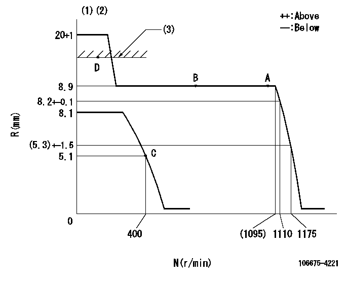
N:Pump speed
R:Rack position (mm)
(1)Notch fixed: K
(2)Tolerance for racks not indicated: +-0.05mm.
(3)RACK LIMIT
----------
K=25
----------
----------
K=25
----------
Speed control lever angle
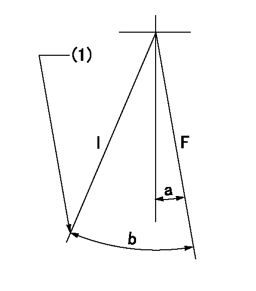
F:Full speed
I:Idle
(1)Stopper bolt setting
----------
----------
a=20deg+-5deg b=(28deg)+-5deg
----------
----------
a=20deg+-5deg b=(28deg)+-5deg
Stop lever angle
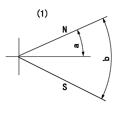
N:Pump normal
S:Stop the pump.
(1)No return spring
----------
----------
a=26.5deg+-5deg b=53deg+-5deg
----------
----------
a=26.5deg+-5deg b=53deg+-5deg
Timing setting
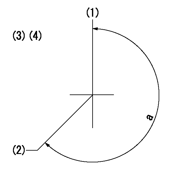
(1)Pump vertical direction
(2)Coupling's key groove position at No 1 cylinder's beginning of injection
(3)-
(4)-
----------
----------
a=(260deg)
----------
----------
a=(260deg)
Information:
Test 1 - Overspeed Switch (OS)
Table 1
Overspeed Switch (OS)
Step Engine RPM Action Correct Result
A 25 + 5 rpm less than 75% Overspeed Verify rpm Press the 75% Verify button No engine shutdown
B 25 + 5 rpm more than 75% Overspeed Verify rpm Press the 75% Verify button Air and fuel shutoff
C Manually reset the air shutoff lever at the top of the air inlet, if equipped. Press the ESS reset button. Test 2 - Emergency Stop Switch (ES)
Table 2
Emergency Stop Switch (ES)
Step Engine RPM Action Correct Result
A Any rpm above the crank terminate rpm Press the push button for the emergency stop switch Air and fuel shutoff
B Manually reset the air shutoff lever at the top of the air inlet, if equipped. Turn ES switch in the dirction that is shown on the face of the push button in order to reset the switch. Test 3 - Normal Stop Switch (NSS)
Table 3
Normal Stop Switch (NSS)
Step Engine RPM Action Correct Result
A Any rpm above the crank terminate rpm Push the normal stop switch (NSS) Fuel shutoff Test 4 - Water Temperature Contactor Switch
Table 4
Water Temperature Contactor Switch (WTS)
Step Engine RPM Action Correct Result
A Any rpm above the crank terminate rpm Place a jumper across terminals TS-2 and TS-7. Fuel shutoff
B Remove the jumper from terminals TS-2 and TS-7. Test 5 - Oil Pressure Switch (OPS1)
Table 5
Oil Pressure Switch (OPS1)
Step Engine RPM Action Correct Result
A Any rpm above the crank terminate rpm Place a jumper across terminals OPS1-1 and OPS1-3. Fuel shutoff
B Remove the jumper from terminals OPS1-1 and OPS1-3. Test 6 - Oil Pressure Switch (OPS2)
Table 6
Oil Pressure Switch (OPS2)
Step Engine RPM Action Correct Result
A 25 + 5 rpm less than the setting for the oil step speed Place a jumper across terminals OPS2-1 and OPS2-3. No engine shutdown.
B 25 + 5 rpm more than the setting for the oil step speed Place a jumper across terminals OPS2-1 and OPS2-3. Fuel shutoff 9 seconds after the oil step speed is reached.
C Remove the jumper from across terminals OPS2-1 and OPS2-3.
Have questions with 106675-4221?
Group cross 106675-4221 ZEXEL
Komatsu
106675-4221
9 400 617 385
6211711681
INJECTION-PUMP ASSEMBLY
S6D140
S6D140