Information injection-pump assembly
ZEXEL
106675-4220
1066754220
KOMATSU
6211711680
6211711680

Rating:
Cross reference number
ZEXEL
106675-4220
1066754220
KOMATSU
6211711680
6211711680
Zexel num
Bosch num
Firm num
Name
Calibration Data:
Adjustment conditions
Test oil
1404 Test oil ISO4113 or {SAEJ967d}
1404 Test oil ISO4113 or {SAEJ967d}
Test oil temperature
degC
40
40
45
Nozzle and nozzle holder
105780-8140
Bosch type code
EF8511/9A
Nozzle
105780-0000
Bosch type code
DN12SD12T
Nozzle holder
105780-2080
Bosch type code
EF8511/9
Opening pressure
MPa
17.2
Opening pressure
kgf/cm2
175
Injection pipe
Outer diameter - inner diameter - length (mm) mm 8-3-600
Outer diameter - inner diameter - length (mm) mm 8-3-600
Overflow valve
131424-3420
Overflow valve opening pressure
kPa
255
221
289
Overflow valve opening pressure
kgf/cm2
2.6
2.25
2.95
Tester oil delivery pressure
kPa
157
157
157
Tester oil delivery pressure
kgf/cm2
1.6
1.6
1.6
Direction of rotation (viewed from drive side)
Right R
Right R
Injection timing adjustment
Direction of rotation (viewed from drive side)
Right R
Right R
Injection order
1-5-3-6-
2-4
Pre-stroke
mm
4.3
4.25
4.35
Beginning of injection position
Drive side NO.1
Drive side NO.1
Difference between angles 1
Cal 1-5 deg. 60 59.5 60.5
Cal 1-5 deg. 60 59.5 60.5
Difference between angles 2
Cal 1-3 deg. 120 119.5 120.5
Cal 1-3 deg. 120 119.5 120.5
Difference between angles 3
Cal 1-6 deg. 180 179.5 180.5
Cal 1-6 deg. 180 179.5 180.5
Difference between angles 4
Cyl.1-2 deg. 240 239.5 240.5
Cyl.1-2 deg. 240 239.5 240.5
Difference between angles 5
Cal 1-4 deg. 300 299.5 300.5
Cal 1-4 deg. 300 299.5 300.5
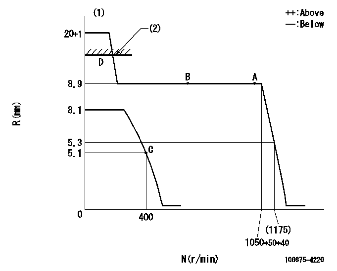
Injection quantity adjustment
Adjusting point
A
Rack position
8.9
Pump speed
r/min
1050
1050
1050
Average injection quantity
mm3/st.
145.5
141.5
149.5
Max. variation between cylinders
%
0
-3
3
Basic
*
Fixing the lever
*
Injection quantity adjustment_02
Adjusting point
C
Rack position
5.1+-0.5
Pump speed
r/min
400
400
400
Average injection quantity
mm3/st.
18
16.5
19.5
Max. variation between cylinders
%
0
-15
15
Fixing the rack
*
Injection quantity adjustment_03
Adjusting point
D
Rack position
-
Pump speed
r/min
100
100
100
Average injection quantity
mm3/st.
200
190
210
Fixing the lever
*
Rack limit
*
Test data Ex:
Governor adjustment
N:Pump speed
R:Rack position (mm)
(1)Notch fixed: K
(2)RACK LIMIT
----------
K=25
----------
----------
K=25
----------
Speed control lever angle
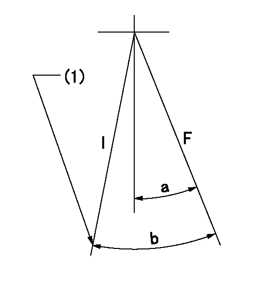
F:Full speed
I:Idle
(1)Stopper bolt setting
----------
----------
a=20deg+-5deg b=(28deg)+-5deg
----------
----------
a=20deg+-5deg b=(28deg)+-5deg
Stop lever angle

N:Pump normal
S:Stop the pump.
----------
----------
a=26.5deg+-5deg b=53deg+-5deg
----------
----------
a=26.5deg+-5deg b=53deg+-5deg
Timing setting
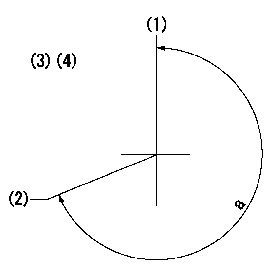
(1)Pump vertical direction
(2)Coupling's key groove position at No 1 cylinder's beginning of injection
(3)-
(4)-
----------
----------
a=(260deg)
----------
----------
a=(260deg)
Information:
Problem 4
The starting motor remains engaged or the starting motor continues to run after the engine is running.
Check the components of the starting circuit.
Measure the voltages at terminal (TS-26) of the junction box while the engine is running.Result
The voltage at the terminal is zero volts.The problem is in the starting motor (SM), the pinion solenoid (PS), or the magnetic switch (MS). Repair the faulty component. STOP.
The voltage at the terminal is between 15 volts and 32 volts.The START terminals of the start/stop switch are normally closed. This is normal for an automatic start system. In a manual start system, the switches should be normally open. The switch is on terminals (SSS-1) and (SSS-2) for a normal start/stop switch. Repair the faulty switch. STOP.Problem 5
The engine shutdown occurs after the engine runs for more than 3 minutes.
Check the protection switches.
Remove the jumper that is between terminals (TS-9) and (TS-10) of the junction box.
If the engine is equipped with a low oil pressure indicator, disconnect the diode that is between terminals (TS-8) and (TS-10). The cathode lead of the diode should be connected to terminal (TS-10).
If the engine is equipped with a low oil pressure indicator, ensure that a jumper is not installed between terminals (TS-8) and (TS-9).
Start the engine.
Reconnect the jumper that is between terminals (TS-9) and (TS-10) of the junction box after the test is completed.Result
The engine starts and the engine runs.The problem is in the oil pressure switch or the water temperature contactor switch. Go to Step 5 of "Problem 1".
The engine starts but engine shutdown occurs immediately.Go to Step 1 of "Problem 3".
The engine starts and the engine runs but engine shutdown occurs after the engine runs for more than 3 minutes.Go to Step 2.
The engine cranks but the engine does not start.Go to Step 1 of "Problem 1".
Check the start/stop switch and slave relay (SR1).
Disconnect the wire in the junction box that connects terminal (SR1-85) of the slave relay (SR1) to terminal (TD-7) of the time delay relay (TD).
Crank the engine. Activate the emergency stop switch, if necessary.Result
The engine starts and the engine runs.The start/stop switch has a short circuit or a wiring problem is causing a voltage at terminal (TD-7). Reconnect the wire to the terminal. STOP.
Engine shutdown still occurs after several minutes.The contacts of (SR1) periodically close. The problem may also be with the governor or the fuel supply to the engine. Refer to the Engine Service Manual. If a 2301A Electric Governor is used, the SR1 contacts may be opening. Refer to 2301A Electric Governor Service Manual, SENR3585. Test SR1. Refer to Testing and Adjusting, "Slave Relay Test".Problem 6
Engine shutdown does not occur when a fault is detected.
Check the protection switches and the crank terminate switch of the electronic speed switch.
Reset circuit breaker (CB7).
Start the engine and run the engine at low idle.
Contact with electrical components can cause injury or death.Remove all jewelry and avoid contact with electrical components. Use properly insulated tools when working on the junction box of an