Information injection-pump assembly
BOSCH
9 400 612 378
9400612378
ZEXEL
106675-4213
1066754213
KOMATSU
6152711443
6152711443
Rating:
Service parts 106675-4213 INJECTION-PUMP ASSEMBLY:
1.
_
5.
AUTOM. ADVANCE MECHANIS
7.
COUPLING PLATE
8.
_
9.
_
11.
Nozzle and Holder
6152-11-3100
12.
Open Pre:MPa(Kqf/cm2)
24.5{250}
15.
NOZZLE SET
Include in #1:
106675-4213
as INJECTION-PUMP ASSEMBLY
Cross reference number
BOSCH
9 400 612 378
9400612378
ZEXEL
106675-4213
1066754213
KOMATSU
6152711443
6152711443
Zexel num
Bosch num
Firm num
Name
106675-4213
9 400 612 378
6152711443 KOMATSU
INJECTION-PUMP ASSEMBLY
SA6D125 K 14CA INJECTION PUMP ASSY PE6P,6PD PE
SA6D125 K 14CA INJECTION PUMP ASSY PE6P,6PD PE
Calibration Data:
Adjustment conditions
Test oil
1404 Test oil ISO4113 or {SAEJ967d}
1404 Test oil ISO4113 or {SAEJ967d}
Test oil temperature
degC
40
40
45
Nozzle and nozzle holder
105780-8130
Bosch type code
EFEP215A
Nozzle
105780-0050
Bosch type code
DN6TD1199NP1T
Nozzle holder
105780-2090
Bosch type code
EFEP215
Opening pressure
MPa
17.2
Opening pressure
kgf/cm2
175
Injection pipe
Outer diameter - inner diameter - length (mm) mm 8-3-600
Outer diameter - inner diameter - length (mm) mm 8-3-600
Overflow valve
131425-2120
Overflow valve opening pressure
kPa
157
123
191
Overflow valve opening pressure
kgf/cm2
1.6
1.25
1.95
Tester oil delivery pressure
kPa
157
157
157
Tester oil delivery pressure
kgf/cm2
1.6
1.6
1.6
Direction of rotation (viewed from drive side)
Left L
Left L
Injection timing adjustment
Direction of rotation (viewed from drive side)
Left L
Left L
Injection order
1-5-3-6-
2-4
Pre-stroke
mm
3.8
3.75
3.85
Beginning of injection position
Drive side NO.1
Drive side NO.1
Difference between angles 1
Cal 1-5 deg. 60 59.5 60.5
Cal 1-5 deg. 60 59.5 60.5
Difference between angles 2
Cal 1-3 deg. 120 119.5 120.5
Cal 1-3 deg. 120 119.5 120.5
Difference between angles 3
Cal 1-6 deg. 180 179.5 180.5
Cal 1-6 deg. 180 179.5 180.5
Difference between angles 4
Cyl.1-2 deg. 240 239.5 240.5
Cyl.1-2 deg. 240 239.5 240.5
Difference between angles 5
Cal 1-4 deg. 300 299.5 300.5
Cal 1-4 deg. 300 299.5 300.5
Injection quantity adjustment
Adjusting point
A
Rack position
12.1
Pump speed
r/min
900
900
900
Average injection quantity
mm3/st.
311
308
314
Max. variation between cylinders
%
0
-3
3
Basic
*
Fixing the lever
*
Injection quantity adjustment_02
Adjusting point
C
Rack position
4.7+-0.5
Pump speed
r/min
375
375
375
Average injection quantity
mm3/st.
15
13.5
16.5
Max. variation between cylinders
%
0
-15
15
Fixing the rack
*
Test data Ex:
Governor adjustment
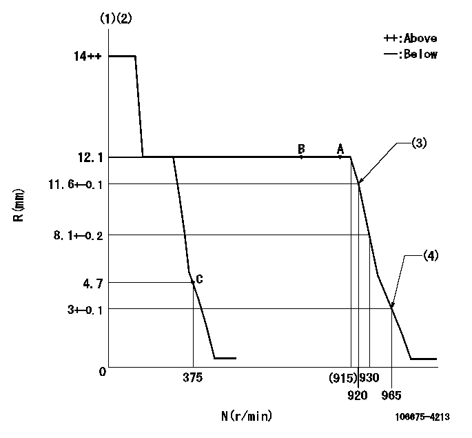
N:Pump speed
R:Rack position (mm)
(1)Target notch: K
(2)Tolerance for racks not indicated: +-0.05mm.
(3)Main spring setting
(4)Set idle sub-spring
----------
K=8
----------
----------
K=8
----------
Speed control lever angle
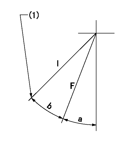
F:Full speed
I:Idle
(1)Stopper bolt setting
----------
----------
a=5deg+-5deg b=21deg+-5deg
----------
----------
a=5deg+-5deg b=21deg+-5deg
Stop lever angle
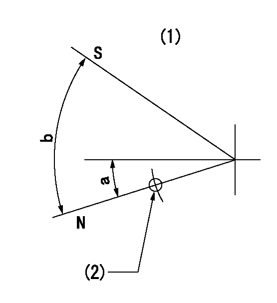
N:Pump normal
S:Stop the pump.
(1)No return spring
(2)At hole above left hand side R = aa
----------
aa=27mm
----------
a=26.5deg+-5deg b=53deg+-5deg
----------
aa=27mm
----------
a=26.5deg+-5deg b=53deg+-5deg
Timing setting

(1)Pump vertical direction
(2)Coupling's key groove position at No 1 cylinder's beginning of injection
(3)-
(4)-
----------
----------
a=(150deg)
----------
----------
a=(150deg)
Information:
Problem 5
The engine shutdown occurs after the engine runs for more than 3 minutes.
Check the overspeed setting on the electronic speed switch (ESS).
Observe the indicator lamp on the ESS.
Reset the air shutoff lever, if equipped.
Crank the engine. Stop the engine with the emergency stop switch, if trouble occurs.Result
The indicator lamp on the ESS is turned on.Overspeed is indicated as the cause of the engine shutdown. Press the "RESET" button of the ESS. Find the cause of the overspeed. Refer to Testing and Adjusting, "Overspeed Verification Test" and Testing and Adjusting, "Overspeed Calibration". If the overspeed is adjusted properly and the problem persists, check the shielded cable. Only the shield should be connected to terminal 2 on the ESS. STOP.
The indicator lamp is turned off.Go to Step 2.
Check the protection switches.
Remove the jumper that is between terminals (TS-9) and (TS-10) of the junction box.
Crank the engine. Stop the engine with the emergency stop switch, if trouble occurs.Result
The engine starts and the engine runs.The problem is in the oil pressure switches or the water temperature contactor switch. Go to Step 8 of "Problem 1".
The engine starts but engine shutdown occurs immediately.Go to Step 1 of "Problem 3".
The engine starts and the engine runs but engine shutdown occurs after the engine runs for more than 3 minutes.Go to Step 3.
The engine cranks but the engine does not start.Go to Step 1 of "Problem 1".
Check the start/stop switch.
Disconnect the wire in the junction box that connects terminal (SR1-85) of the slave relay (SR1) to terminal (TD-7) of the time delay relay (TD).
Disconnect the wire from terminal (TD-7) and insulate the exposed wire.
Crank the engine. Stop the engine with the emergency stop switch, if trouble occurs.Result
The engine starts and the engine runs.The start/stop switch has a short circuit or a wiring problem is causing a voltage at terminal (TD-7). Reconnect the wire to the terminal.
Check the start/stop switch.
Disconnect the wire that runs from the STOP position of terminal (SSS-6) to terminal (TD-6). Terminal (SSS-6) is on the start/stop switch.
Disconnect the wire at terminal (TD-7).
Crank the engine. Stop the engine with the emergency stop switch, if trouble occurs.Result
The engine starts and the engine runs.The start/stop switch is faulty. Replace the switch. STOP.
Engine shutdown still occurs.Reconnect the wire to terminal (TD-7). Go to Step 5
Check the slave relay (SR1).
Disconnect the wire that connects terminal (TS-10) of the junction box to terminal (TD-6) of the time delay relay.
Disconnect the wire at terminal (TD-6).
Crank the engine. Stop the engine with the emergency stop switch, if trouble occurs.Result
The engine starts and the engine runs.The start/stop switch is faulty. Replace the start/stop switch. STOP.
Engine shutdown still occurs.The contacts of SR1 periodically close. The problem may also be with the governor or the fuel supply to the engine. Refer to the Engine Service Manual. If a 2301A Electric Governor is used, the SR1 contacts may be opening. Refer to 2301A Electric Governor Service Manual, SENR3585. Test SR1. Refer to Testing and Adjusting, "Slave Relay Test".Problem 6
Engine shutdown does not occur
Have questions with 106675-4213?
Group cross 106675-4213 ZEXEL
Komatsu
106675-4213
9 400 612 378
6152711443
INJECTION-PUMP ASSEMBLY
SA6D125
SA6D125