Information injection-pump assembly
BOSCH
9 400 617 352
9400617352
ZEXEL
106673-7710
1066737710
MITSUBISHI
ME152404
me152404
Rating:
Cross reference number
BOSCH
9 400 617 352
9400617352
ZEXEL
106673-7710
1066737710
MITSUBISHI
ME152404
me152404
Zexel num
Bosch num
Firm num
Name
106673-7710
9 400 617 352
ME152404 MITSUBISHI
INJECTION-PUMP ASSEMBLY
6D24 K
6D24 K
Calibration Data:
Adjustment conditions
Test oil
1404 Test oil ISO4113 or {SAEJ967d}
1404 Test oil ISO4113 or {SAEJ967d}
Test oil temperature
degC
40
40
45
Nozzle and nozzle holder
105780-8250
Bosch type code
1 688 901 101
Nozzle
105780-0120
Bosch type code
1 688 901 990
Nozzle holder
105780-2190
Opening pressure
MPa
20.7
Opening pressure
kgf/cm2
211
Injection pipe
Outer diameter - inner diameter - length (mm) mm 8-3-600
Outer diameter - inner diameter - length (mm) mm 8-3-600
Overflow valve
131425-0220
Overflow valve opening pressure
kPa
157
123
191
Overflow valve opening pressure
kgf/cm2
1.6
1.25
1.95
Tester oil delivery pressure
kPa
255
255
255
Tester oil delivery pressure
kgf/cm2
2.6
2.6
2.6
Direction of rotation (viewed from drive side)
Right R
Right R
Injection timing adjustment
Direction of rotation (viewed from drive side)
Right R
Right R
Injection order
1-5-3-6-
2-4
Pre-stroke
mm
3.9
3.85
3.95
Beginning of injection position
Governor side NO.1
Governor side NO.1
Difference between angles 1
Cal 1-5 deg. 60 59.5 60.5
Cal 1-5 deg. 60 59.5 60.5
Difference between angles 2
Cal 1-3 deg. 120 119.5 120.5
Cal 1-3 deg. 120 119.5 120.5
Difference between angles 3
Cal 1-6 deg. 180 179.5 180.5
Cal 1-6 deg. 180 179.5 180.5
Difference between angles 4
Cyl.1-2 deg. 240 239.5 240.5
Cyl.1-2 deg. 240 239.5 240.5
Difference between angles 5
Cal 1-4 deg. 300 299.5 300.5
Cal 1-4 deg. 300 299.5 300.5
Injection quantity adjustment
Adjusting point
-
Rack position
11.9
Pump speed
r/min
700
700
700
Each cylinder's injection qty
mm3/st.
118.5
115.5
121.5
Basic
*
Fixing the rack
*
Standard for adjustment of the maximum variation between cylinders
*
Injection quantity adjustment_02
Adjusting point
Z
Rack position
8.5+-0.5
Pump speed
r/min
410
410
410
Each cylinder's injection qty
mm3/st.
15.8
13.4
18.2
Fixing the rack
*
Standard for adjustment of the maximum variation between cylinders
*
Injection quantity adjustment_03
Adjusting point
A
Rack position
R1(11.9)
Pump speed
r/min
700
700
700
Average injection quantity
mm3/st.
118.5
117.5
119.5
Basic
*
Fixing the lever
*
Injection quantity adjustment_04
Adjusting point
B
Rack position
R1+0.9
Pump speed
r/min
1100
1100
1100
Average injection quantity
mm3/st.
117
113
121
Fixing the lever
*
Injection quantity adjustment_05
Adjusting point
C
Rack position
(R1+0.7)
Pump speed
r/min
900
900
900
Average injection quantity
mm3/st.
124
120
128
Fixing the lever
*
Injection quantity adjustment_06
Adjusting point
D
Rack position
R1-0.65
Pump speed
r/min
500
500
500
Average injection quantity
mm3/st.
112.5
106.5
118.5
Fixing the lever
*
Timer adjustment
Pump speed
r/min
800--
Advance angle
deg.
0
0
0
Remarks
Start
Start
Timer adjustment_02
Pump speed
r/min
750
Advance angle
deg.
0.5
Timer adjustment_03
Pump speed
r/min
1100
Advance angle
deg.
2
1.5
2.5
Remarks
Finish
Finish
Test data Ex:
Governor adjustment
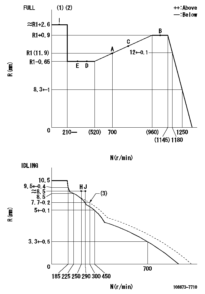
N:Pump speed
R:Rack position (mm)
(1)Torque cam stamping: T1
(2)Tolerance for racks not indicated: +-0.05mm.
(3)Damper spring setting
----------
T1=AE41
----------
----------
T1=AE41
----------
Speed control lever angle
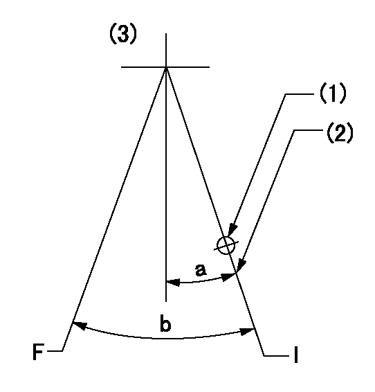
F:Full speed
I:Idle
(1)Use the hole at R = aa
(2)Stopper bolt setting
(3)Viewed from feed pump side.
----------
aa=37.5mm
----------
a=1deg+-5deg b=(36.5deg)+-3deg
----------
aa=37.5mm
----------
a=1deg+-5deg b=(36.5deg)+-3deg
Stop lever angle
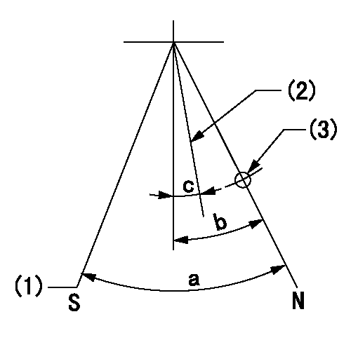
N:Pump normal
S:Stop the pump.
(1)At pump speed aa and rack position bb, set the stopper bolt. (Confirm non-injection.)
(2)Normal engine position (equivalent to R = cc).
(3)Use the hole above R = dd
----------
aa=1100r/min bb=3.5+-0.3mm cc=18mm dd=54mm
----------
a=41deg+-5deg b=29.5deg+-5deg c=(20.5deg)+-5deg
----------
aa=1100r/min bb=3.5+-0.3mm cc=18mm dd=54mm
----------
a=41deg+-5deg b=29.5deg+-5deg c=(20.5deg)+-5deg
0000001501 MICRO SWITCH
Adjustment of the micro-switch
Adjust the bolt to obtain the following lever position when the micro-switch is ON.
(1)Speed N1
(2)Rack position Ra
----------
N1=325r/min Ra=8.1+-0.1mm
----------
----------
N1=325r/min Ra=8.1+-0.1mm
----------
Timing setting

(1)Pump vertical direction
(2)Coupling's key groove position at No 1 cylinder's beginning of injection
(3)B.T.D.C.: aa
(4)-
----------
aa=12deg
----------
a=(8deg)
----------
aa=12deg
----------
a=(8deg)
Information:
21Mar2016
U-141
A-108
D-125
O-121
Parts stock action only
PRODUCT IMPROVEMENT PROGRAM FOR REMOVING CERTAIN 341-2378 INJECTOR WIRING HARNESSES FROM DEALER PART STOCK
1408 7750 PI70613
Caterpillar’s obligations under this Service Letter are subject to, and shall not apply in contravention of, the laws, rules, regulations, directives, ordinances, orders, or statutes of the United States, or of any other applicable jurisdiction, without recourse or liability with respect to Caterpillar.
When submitting claim for Parts Stock Action, Use the appropriate 99Z as the s/n, the appropriate Service Letter Program Number as the Part number in the Part Causing Failure field, "7751" as the Group Number, "56" as the Description Code.
The information supplied in this service letter may not be valid after the termination date of this program.Do not perform the work outlined in this Service Letter after the termination date without first contacting your Caterpillar product analyst.
TERMINATION DATE
30Jun2016
PROBLEM
The 341-2378 Injector Wiring Harness may cause an intermittent injector signal that may cause an injector diagnostic code. The manufacturing process has been improved.
ACTION REQUIRED
Known good 341-2378 Injector Wiring Harnesses have a blue tie strap around the harness, and have been manufactured with an improved process. Do not remove a harness that has a blue tie strap around the wiring harness from dealer parts stock.
Remove all 341-2378 Injector Wiring Harnesses manufactured without a blue tie strap attached to the wiring harness from dealer parts stock.
Image 1 shows the harness with a blue tie strap on the braid.
Image1
SERVICE CLAIM ALLOWANCES
Submit one claim for all parts removed from dealer parts stock.
PARTS DISPOSITION
Handle the parts in accordance with your Warranty Bulletin on warranty parts handling.
Have questions with 106673-7710?
Group cross 106673-7710 ZEXEL
Mitsubishi
106673-7710
9 400 617 352
ME152404
INJECTION-PUMP ASSEMBLY
6D24
6D24