Information injection-pump assembly
BOSCH
9 400 617 351
9400617351
ZEXEL
106673-7701
1066737701
MITSUBISHI
ME152267
me152267
Rating:
Cross reference number
BOSCH
9 400 617 351
9400617351
ZEXEL
106673-7701
1066737701
MITSUBISHI
ME152267
me152267
Zexel num
Bosch num
Firm num
Name
106673-7701
9 400 617 351
ME152267 MITSUBISHI
INJECTION-PUMP ASSEMBLY
6D24T1 K
6D24T1 K
Calibration Data:
Adjustment conditions
Test oil
1404 Test oil ISO4113 or {SAEJ967d}
1404 Test oil ISO4113 or {SAEJ967d}
Test oil temperature
degC
40
40
45
Nozzle and nozzle holder
105780-8250
Bosch type code
1 688 901 101
Nozzle
105780-0120
Bosch type code
1 688 901 990
Nozzle holder
105780-2190
Opening pressure
MPa
20.7
Opening pressure
kgf/cm2
211
Injection pipe
Outer diameter - inner diameter - length (mm) mm 8-3-600
Outer diameter - inner diameter - length (mm) mm 8-3-600
Overflow valve
131425-0220
Overflow valve opening pressure
kPa
157
123
191
Overflow valve opening pressure
kgf/cm2
1.6
1.25
1.95
Tester oil delivery pressure
kPa
255
255
255
Tester oil delivery pressure
kgf/cm2
2.6
2.6
2.6
Direction of rotation (viewed from drive side)
Right R
Right R
Injection timing adjustment
Direction of rotation (viewed from drive side)
Right R
Right R
Injection order
1-5-3-6-
2-4
Pre-stroke
mm
3.9
3.85
3.95
Beginning of injection position
Governor side NO.1
Governor side NO.1
Difference between angles 1
Cal 1-5 deg. 60 59.5 60.5
Cal 1-5 deg. 60 59.5 60.5
Difference between angles 2
Cal 1-3 deg. 120 119.5 120.5
Cal 1-3 deg. 120 119.5 120.5
Difference between angles 3
Cal 1-6 deg. 180 179.5 180.5
Cal 1-6 deg. 180 179.5 180.5
Difference between angles 4
Cyl.1-2 deg. 240 239.5 240.5
Cyl.1-2 deg. 240 239.5 240.5
Difference between angles 5
Cal 1-4 deg. 300 299.5 300.5
Cal 1-4 deg. 300 299.5 300.5
Injection quantity adjustment
Adjusting point
-
Rack position
12.9
Pump speed
r/min
700
700
700
Each cylinder's injection qty
mm3/st.
152.5
148.7
156.3
Basic
*
Fixing the rack
*
Standard for adjustment of the maximum variation between cylinders
*
Injection quantity adjustment_02
Adjusting point
Z
Rack position
8+-0.5
Pump speed
r/min
410
410
410
Each cylinder's injection qty
mm3/st.
21
17.8
24.2
Fixing the rack
*
Standard for adjustment of the maximum variation between cylinders
*
Injection quantity adjustment_03
Adjusting point
A
Rack position
R1(12.9)
Pump speed
r/min
700
700
700
Average injection quantity
mm3/st.
152.5
151.5
153.5
Basic
*
Fixing the lever
*
Boost pressure
kPa
24
24
Boost pressure
mmHg
180
180
Injection quantity adjustment_04
Adjusting point
B
Rack position
R1+0.95
Pump speed
r/min
1100
1100
1100
Average injection quantity
mm3/st.
143
139
147
Fixing the lever
*
Boost pressure
kPa
24
24
Boost pressure
mmHg
180
180
Injection quantity adjustment_05
Adjusting point
C
Rack position
(R1-0.7)
Pump speed
r/min
500
500
500
Average injection quantity
mm3/st.
149.5
143.5
155.5
Fixing the lever
*
Boost pressure
kPa
24
24
Boost pressure
mmHg
180
180
Injection quantity adjustment_06
Adjusting point
D
Rack position
(R2-1.5)
Pump speed
r/min
300
300
300
Average injection quantity
mm3/st.
103
101
105
Fixing the lever
*
Boost pressure
kPa
0
0
0
Boost pressure
mmHg
0
0
0
Boost compensator adjustment
Pump speed
r/min
300
300
300
Rack position
(R2-1.5)
Boost pressure
kPa
4
2.7
5.3
Boost pressure
mmHg
30
20
40
Boost compensator adjustment_02
Pump speed
r/min
300
300
300
Rack position
R2(R1-1)
Boost pressure
kPa
10.7
10.7
10.7
Boost pressure
mmHg
80
80
80
Test data Ex:
Governor adjustment
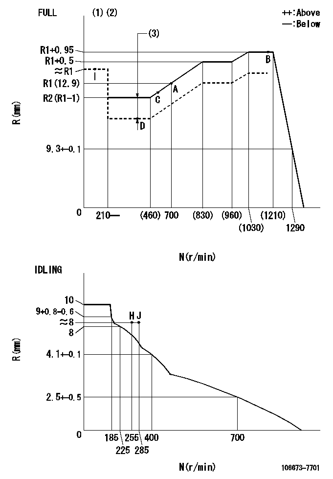
N:Pump speed
R:Rack position (mm)
(1)Torque cam stamping: T1
(2)Tolerance for racks not indicated: +-0.05mm.
(3)Boost compensator stroke: BCL
----------
T1=AE93 BCL=(1.5)+-0.1mm
----------
----------
T1=AE93 BCL=(1.5)+-0.1mm
----------
Timer adjustment

(1)Adjusting range
(2)Step response time
(N): Speed of the pump
(L): Load
(theta) Advance angle
(Srd1) Step response time 1
(Srd2) Step response time 2
1. Adjusting conditions for the variable timer
(1)Adjust the clearance between the pickup and the protrusion to L.
----------
L=1-0.2(mm) N2=800r/min C2=(10deg) t1=2.5--sec. t2=2.5--sec.
----------
N1=750++r/min P1=0kPa(0kgf/cm2) P2=392kPa(4kgf/cm2) C1=10+-0.3deg R01=0/4load R02=4/4load
----------
L=1-0.2(mm) N2=800r/min C2=(10deg) t1=2.5--sec. t2=2.5--sec.
----------
N1=750++r/min P1=0kPa(0kgf/cm2) P2=392kPa(4kgf/cm2) C1=10+-0.3deg R01=0/4load R02=4/4load
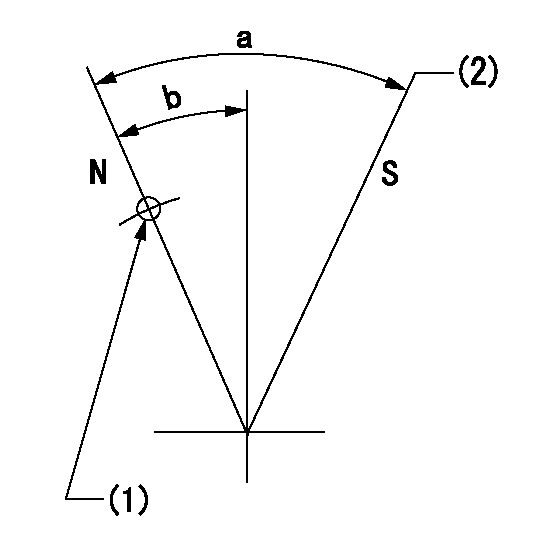
Speed control lever angle

F:Full speed
I:Idle
(1)Use the pin at R = aa
(2)Stopper bolt set position 'H'
(3)Viewed from feed pump side.
----------
aa=45mm
----------
a=30deg+-5deg b=(42deg)+-3deg
----------
aa=45mm
----------
a=30deg+-5deg b=(42deg)+-3deg
Stop lever angle
N:Pump normal
S:Stop the pump.
(1)Use the hole at R = aa
(2)Set the stopper bolt so that speed = bb and rack position = cc. (Confirm non-injection.)
----------
aa=33.5mm bb=1100r/min cc=3.5+-0.3mm
----------
a=40deg+-5deg b=25.5deg+-5deg
----------
aa=33.5mm bb=1100r/min cc=3.5+-0.3mm
----------
a=40deg+-5deg b=25.5deg+-5deg
0000001501 RACK SENSOR

(VR) measurement voltage
(I) Part number of the control unit
(G) Apply red paint.
(H): End surface of the pump
1. Rack sensor adjustment (-0620)
(1)Fix the speed control lever at the full position
(2)Set the speed to N1 r/min.
(If the boost compensator is provided, apply boost pressure.)
(3)Adjust the bobbin (A) so that the rack sensor's output voltage is VR+-0.01.
(4)At that time, rack position must be Ra.
(5)Apply G at two places.
Connecting part between the joint (B) and the nut (F)
Connecting part between the joint (B) and the end surface of the pump (H)
----------
N1=1100r/min Ra=R1(12.9)+0.95mm
----------
----------
N1=1100r/min Ra=R1(12.9)+0.95mm
----------
0000001601 MICRO SWITCH
Adjustment of the micro-switch
Adjust the bolt to obtain the following lever position when the micro-switch is ON.
(1)Speed N1
(2)Rack position Ra
----------
N1=325r/min Ra=7.6+-0.1mm
----------
----------
N1=325r/min Ra=7.6+-0.1mm
----------
0000001701 SPEED SENSOR
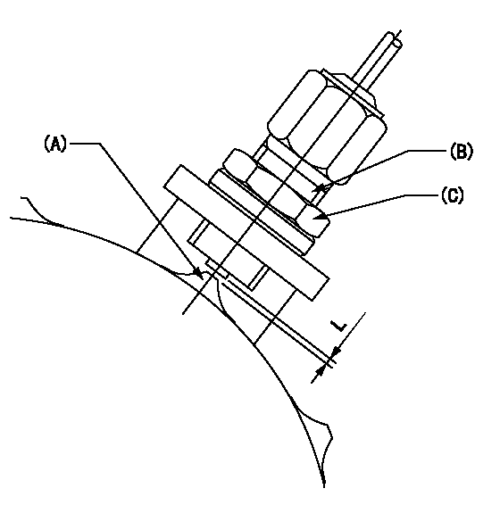
(A) Flyweight projection
(B) Pickup sensor
(c) Lock nut
Speed sensor installation
(1)Install the speed sensor so that the clearance between the sensor and the flyweight projection is L.
(This gap is the gap when the pickup sensor is returned 1 turn from where it contacts the flyweight tooth.)
----------
L=0.8~1mm
----------
----------
L=0.8~1mm
----------
Timing setting

(1)Pump vertical direction
(2)Coupling's key groove position at No 1 cylinder's beginning of injection
(3)B.T.D.C.: aa
(4)-
----------
aa=5deg
----------
a=(2deg)
----------
aa=5deg
----------
a=(2deg)
Information:
SERVICE CLAIM ALLOWANCES
****Parts Stock****
Submit one claim for all parts removed from dealer parts stock.
****Affected Product****
Product smu/age whichever comes first Caterpillar Dealer Suggested Customer Suggested
Parts % Labor Hrs% Parts % Labor Hrs% Parts % Labor Hrs%
0-3000 hrs,
0-48 mo 100.0% 100.0% 0.0% 0.0% 0.0% 0.0%
This is a 4.0-hour job
For After failure, and additional 9.0 hours are allowed. A maximum of $100 will be allowed for machining of cylinder head face to achieve required surface finish after failure.
PARTS DISPOSITION
****Parts Stock****
Handle the parts in accordance with your Warranty Bulletin on warranty parts handling.
****Affected Product****
Handle the parts in accordance with your Warranty Bulletin on warranty parts handling.
Rework Procedure
If the head gasket has failed follow the rework procedure for both head gasket replacement and for fuel injection pump replacement. Check that the fuel pump has not suffered a mechanical failure that has resulted in a head gasket failure, such as mechanical failure of the advance box due to air ingress. Head gasket failure due to mechanical failure of the fuel pump is not covered by this service letter.
If the head gasket has not failed follow the rework procedure for fuel injection pump replacement only.
Head gasket replacement:
Confirm the head gasket has failed through removal of the cylinder head and visual inspection of the gasket. Remove cylinder head ? refer to Disassembly and Assembly, "Cylinder Head - Remove". Confirm head gasket has failed through visual inspection, as per the images shown in Image 1.1.1.
Clean the cylinder head face and the cylinder block face to remove any deposits on the gasket sealing surface using an appropriate cleaner. Do not use abrasive materials to remove the deposits during the cleaning process to ensure that the correct surface flatness is maintained.
Inspect cylinder head for flatness and distortion. Refer to Image 1.1.2 for surface finish. Refer to System Operation Testing and Adjusting, "Cylinder Head ? Inspect" for more information. Resurface the cylinder head if required as per Testing and Adjusting, "Cylinder Head ? Inspect".
Inspect cylinder block for surface finish on the top deck of the cylinder block. Refer to Image 1.1.2 for surface finish. If the cylinder block is within specifications, install a new 258-4946 Cylinder Head Gasket. If the block is not within specification, refer to Reuse And Salvage Guidelines, SEBF8076, "Specifications to Salvage Contact Surfaces of Cylinder Blocks" for more information.
Note: A 369-3705 Cylinder Head Gasket may be required, depending on reuse and salvage guidelines.
Follow Disassembly and Assembly, "Cylinder Head ? Install" with a new gasket as per above information.
Fuel injection pump replacement:
Follow Disassembly and Assembly, "Fuel Injection Pump - Remove - Delphi DP210". Do not reuse the fuel pump. Record removed fuel pump serial number in claim story. The fuel pump serial number is in the format "12345ABC".
Install the new 483-2328 Fuel Pump as per Disassembly and Assembly, "Fuel Injection Pump - Install - Delphi DP210". Record the installed fuel pump serial number in claim story. It is essential to install the fuel injection pump with the correct engine position to achieve the correct fuel injection timing and the
Have questions with 106673-7701?
Group cross 106673-7701 ZEXEL
Mitsubishi
106673-7701
9 400 617 351
ME152267
INJECTION-PUMP ASSEMBLY
6D24T1
6D24T1