Information injection-pump assembly
ZEXEL
106673-7462
1066737462

Rating:
Cross reference number
ZEXEL
106673-7462
1066737462
Zexel num
Bosch num
Firm num
Name
106673-7462
INJECTION-PUMP ASSEMBLY
Calibration Data:
Adjustment conditions
Test oil
1404 Test oil ISO4113 or {SAEJ967d}
1404 Test oil ISO4113 or {SAEJ967d}
Test oil temperature
degC
40
40
45
Nozzle and nozzle holder
105780-8250
Bosch type code
1 688 901 101
Nozzle
105780-0120
Bosch type code
1 688 901 990
Nozzle holder
105780-2190
Opening pressure
MPa
20.7
Opening pressure
kgf/cm2
211
Injection pipe
Outer diameter - inner diameter - length (mm) mm 8-3-600
Outer diameter - inner diameter - length (mm) mm 8-3-600
Overflow valve
131425-0220
Overflow valve opening pressure
kPa
157
123
191
Overflow valve opening pressure
kgf/cm2
1.6
1.25
1.95
Tester oil delivery pressure
kPa
255
255
255
Tester oil delivery pressure
kgf/cm2
2.6
2.6
2.6
Direction of rotation (viewed from drive side)
Right R
Right R
Injection timing adjustment
Direction of rotation (viewed from drive side)
Right R
Right R
Injection order
1-5-3-6-
2-4
Pre-stroke
mm
3.9
3.85
3.95
Beginning of injection position
Governor side NO.1
Governor side NO.1
Difference between angles 1
Cal 1-5 deg. 60 59.5 60.5
Cal 1-5 deg. 60 59.5 60.5
Difference between angles 2
Cal 1-3 deg. 120 119.5 120.5
Cal 1-3 deg. 120 119.5 120.5
Difference between angles 3
Cal 1-6 deg. 180 179.5 180.5
Cal 1-6 deg. 180 179.5 180.5
Difference between angles 4
Cyl.1-2 deg. 240 239.5 240.5
Cyl.1-2 deg. 240 239.5 240.5
Difference between angles 5
Cal 1-4 deg. 300 299.5 300.5
Cal 1-4 deg. 300 299.5 300.5
Injection quantity adjustment
Adjusting point
-
Rack position
13.7
Pump speed
r/min
700
700
700
Each cylinder's injection qty
mm3/st.
172.5
168.2
176.8
Basic
*
Fixing the rack
*
Standard for adjustment of the maximum variation between cylinders
*
Injection quantity adjustment_02
Adjusting point
Z
Rack position
8+-0.5
Pump speed
r/min
390
390
390
Each cylinder's injection qty
mm3/st.
26
22.1
29.9
Fixing the rack
*
Standard for adjustment of the maximum variation between cylinders
*
Injection quantity adjustment_03
Adjusting point
A
Rack position
R1(13.7)
Pump speed
r/min
700
700
700
Average injection quantity
mm3/st.
172.5
170.5
174.5
Basic
*
Fixing the lever
*
Boost pressure
kPa
29.3
29.3
Boost pressure
mmHg
220
220
Injection quantity adjustment_04
Adjusting point
B
Rack position
R1+0.9
Pump speed
r/min
1100
1100
1100
Average injection quantity
mm3/st.
157
153
161
Fixing the lever
*
Boost pressure
kPa
29.3
29.3
Boost pressure
mmHg
220
220
Injection quantity adjustment_05
Adjusting point
C
Rack position
(R1-0.85
)
Pump speed
r/min
500
500
500
Average injection quantity
mm3/st.
171.5
165.5
177.5
Fixing the lever
*
Boost pressure
kPa
29.3
29.3
Boost pressure
mmHg
220
220
Boost compensator adjustment
Pump speed
r/min
250
250
250
Rack position
R2-1.65
Boost pressure
kPa
6.7
5.4
8
Boost pressure
mmHg
50
40
60
Boost compensator adjustment_02
Pump speed
r/min
250
250
250
Rack position
R2[R1-1.
7]
Boost pressure
kPa
16
16
16
Boost pressure
mmHg
120
120
120
Test data Ex:
Governor adjustment
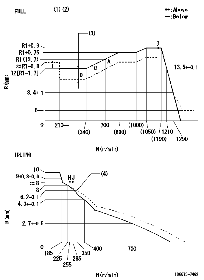
N:Pump speed
R:Rack position (mm)
(1)Torque cam stamping: T1
(2)Tolerance for racks not indicated: +-0.05mm.
(3)Boost compensator stroke: BCL
(4)Damper spring setting
----------
T1=AE17 BCL=1.65+-0.1mm
----------
----------
T1=AE17 BCL=1.65+-0.1mm
----------
Timer adjustment

(1)Adjusting range
(2)Step response time
(N): Speed of the pump
(L): Load
(theta) Advance angle
(Srd1) Step response time 1
(Srd2) Step response time 2
1. Adjusting conditions for the variable timer
(1)Adjust the clearance between the pickup and the protrusion to L.
----------
L=1-0.2(mm) N2=800r/min C2=(10)deg t1=2.5--sec. t2=2.5--sec.
----------
N1=750++r/min P1=0kPa(0kgf/cm2) P2=392kPa(4kgf/cm2) C1=10+-0.3deg R01=0/4load R02=4/4load
----------
L=1-0.2(mm) N2=800r/min C2=(10)deg t1=2.5--sec. t2=2.5--sec.
----------
N1=750++r/min P1=0kPa(0kgf/cm2) P2=392kPa(4kgf/cm2) C1=10+-0.3deg R01=0/4load R02=4/4load
Speed control lever angle
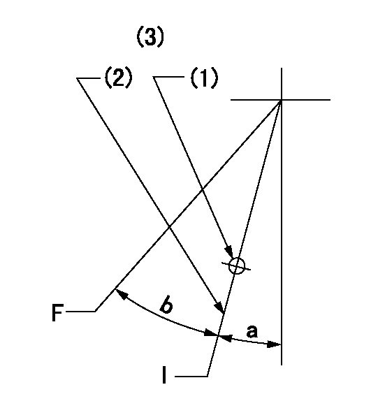
F:Full speed
I:Idle
(1)Use the hole at R = aa
(2)Stopper bolt setting
(3)Viewed from feed pump side.
----------
aa=37.5mm
----------
a=2deg+-5deg b=37deg+-3deg
----------
aa=37.5mm
----------
a=2deg+-5deg b=37deg+-3deg
Stop lever angle
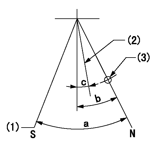
N:Pump normal
S:Stop the pump.
(1)At pump speed aa and rack position bb, set the stopper bolt. (Confirm non-injection.)
(2)Normal engine position (equivalent to R = cc).
(3)Use the hole above R = dd
----------
aa=1100r/min bb=3.5+-0.3mm cc=18mm dd=54mm
----------
a=40deg+-5deg b=29.5deg+-5deg c=(20.5deg)
----------
aa=1100r/min bb=3.5+-0.3mm cc=18mm dd=54mm
----------
a=40deg+-5deg b=29.5deg+-5deg c=(20.5deg)
0000001501 MICRO SWITCH
Adjustment of the micro-switch
Adjust the bolt to obtain the following lever position when the micro-switch is ON.
(1)Speed N1
(2)Rack position Ra
----------
N1=325r/min Ra=7.6+-0.1mm
----------
----------
N1=325r/min Ra=7.6+-0.1mm
----------
0000001601 RACK SENSOR

(VR) measurement voltage
(I) Part number of the control unit
(G) Apply red paint.
(H): End surface of the pump
1. Rack sensor adjustment (-0620)
(1)Fix the speed control lever at the full position
(2)Set the speed to N1 r/min.
(If the boost compensator is provided, apply boost pressure.)
(3)Adjust the bobbin (A) so that the rack sensor's output voltage is VR+-0.01.
(4)At that time, rack position must be Ra.
(5)Apply G at two places.
Connecting part between the joint (B) and the nut (F)
Connecting part between the joint (B) and the end surface of the pump (H)
----------
N1=1100r/min Ra=R1(13.7)+0.9mm
----------
----------
N1=1100r/min Ra=R1(13.7)+0.9mm
----------
Timing setting

(1)Pump vertical direction
(2)Coupling's key groove position at No 1 cylinder's beginning of injection
(3)B.T.D.C.: aa
(4)-
----------
aa=5deg
----------
a=(2deg)
----------
aa=5deg
----------
a=(2deg)
Information:
Start By:a. remove flywheel housing 1. Loosen four bolts (1) approximately 6.4 mm (.25 in). Use Tool (A) to loosen camshaft rear gear (2) from the camshaft.2. Remove Tool (A) and four bolts (1).
If balancer gear (3) is in a position similar to that shown in the picture, the weight on balancer gear (3) will turn down when the camshaft rear gear is removed. To prevent personal injury, hold balancer gear (3) when camshaft rear gear (2) is removed.
3. Remove camshaft rear gear (2). 4. Remove bolt (4), plate (5) and balancer gear (3).5. Inspect the bearing in balancer gear (3). The inside diameter (bore) of a new bearing must be 50.853 to 50.950 mm (2.0021 to 2.0059 in). 6. Use Tooling (B) and a press to remove the bearing from balancer gear (3). 7. Inspect shaft (7) for wear or damage. The outside diameter (new) of shaft (7) must be 50.787 to 50.813 mm (1.9995 to 2.0005 in).8. If a replacement of shaft (7) is necessary, remove bolts (6) and shaft (7) from the cylinder block.Install Camshaft Rear Gear & Balancer
1. Install shaft (7) and four bolts (6) on the cylinder block. 2. Use Tooling (A) to install the bearing in balancer gear (3). Install the bearing so that the bearing joint is on the weight side of the gear within 20 degrees of the centerline as shown. Install the bearing so that it is 1.3 mm (.05 in) from the opposite surface on balancer gear (3). 3. Put clean engine oil on the inside diameter of the bearing in the balancer gear. Install balancer gear (3) and plate (5). Make sure the side of the balancer gear with the weight is toward the cylinder block. Install the bolt (4) that holds the balancer gear in position on the shaft. Check to make sure that there is 0.15 to 0.36 mm (.006 to .014 in) end play between the balancer gear and the shaft.
Be sure the timing "V" marks (8) are aligned when the camshaft rear gear is installed on the camshaft.
4. Engage camshaft rear gear (2) with the dowel on the camshaft. Install bolts (1).5. Tighten bolts (1) to a torque of 23 to 31 N m (17 to 23 lb ft).End By:a. install flywheel housing
Have questions with 106673-7462?
Group cross 106673-7462 ZEXEL
Mitsubishi
Mitsubishi
Mitsubishi
Mitsubishi
106673-7462
INJECTION-PUMP ASSEMBLY