Information injection-pump assembly
ZEXEL
106673-7440
1066737440
Rating:
Cross reference number
ZEXEL
106673-7440
1066737440
Zexel num
Bosch num
Firm num
Name
106673-7440
INJECTION-PUMP ASSEMBLY
Calibration Data:
Adjustment conditions
Test oil
1404 Test oil ISO4113 or {SAEJ967d}
1404 Test oil ISO4113 or {SAEJ967d}
Test oil temperature
degC
40
40
45
Nozzle and nozzle holder
105780-8250
Bosch type code
1 688 901 101
Nozzle
105780-0120
Bosch type code
1 688 901 990
Nozzle holder
105780-2190
Opening pressure
MPa
20.7
Opening pressure
kgf/cm2
211
Injection pipe
Outer diameter - inner diameter - length (mm) mm 8-3-600
Outer diameter - inner diameter - length (mm) mm 8-3-600
Overflow valve
131425-0220
Overflow valve opening pressure
kPa
157
123
191
Overflow valve opening pressure
kgf/cm2
1.6
1.25
1.95
Tester oil delivery pressure
kPa
255
255
255
Tester oil delivery pressure
kgf/cm2
2.6
2.6
2.6
Direction of rotation (viewed from drive side)
Right R
Right R
Injection timing adjustment
Direction of rotation (viewed from drive side)
Right R
Right R
Injection order
1-5-3-6-
2-4
Pre-stroke
mm
3.9
3.85
3.95
Beginning of injection position
Governor side NO.1
Governor side NO.1
Difference between angles 1
Cal 1-5 deg. 60 59.5 60.5
Cal 1-5 deg. 60 59.5 60.5
Difference between angles 2
Cal 1-3 deg. 120 119.5 120.5
Cal 1-3 deg. 120 119.5 120.5
Difference between angles 3
Cal 1-6 deg. 180 179.5 180.5
Cal 1-6 deg. 180 179.5 180.5
Difference between angles 4
Cyl.1-2 deg. 240 239.5 240.5
Cyl.1-2 deg. 240 239.5 240.5
Difference between angles 5
Cal 1-4 deg. 300 299.5 300.5
Cal 1-4 deg. 300 299.5 300.5
Injection quantity adjustment
Adjusting point
-
Rack position
12.7
Pump speed
r/min
700
700
700
Each cylinder's injection qty
mm3/st.
145.5
141.9
149.1
Basic
*
Fixing the rack
*
Standard for adjustment of the maximum variation between cylinders
*
Injection quantity adjustment_02
Adjusting point
Z
Rack position
8+-0.5
Pump speed
r/min
430
430
430
Each cylinder's injection qty
mm3/st.
21
17.8
24.2
Fixing the rack
*
Standard for adjustment of the maximum variation between cylinders
*
Injection quantity adjustment_03
Adjusting point
A
Rack position
R1(12.7)
Pump speed
r/min
700
700
700
Average injection quantity
mm3/st.
145.5
144.5
146.5
Basic
*
Fixing the lever
*
Boost pressure
kPa
23.3
23.3
Boost pressure
mmHg
175
175
Injection quantity adjustment_04
Adjusting point
B
Rack position
R1+1.05
Pump speed
r/min
1100
1100
1100
Average injection quantity
mm3/st.
143.5
139.5
147.5
Fixing the lever
*
Boost pressure
kPa
23.3
23.3
Boost pressure
mmHg
175
175
Injection quantity adjustment_05
Adjusting point
C
Rack position
(R1-0.75
)
Pump speed
r/min
500
500
500
Average injection quantity
mm3/st.
144
138
150
Fixing the lever
*
Boost pressure
kPa
23.3
23.3
Boost pressure
mmHg
175
175
Injection quantity adjustment_06
Adjusting point
D
Rack position
(R2-1.4)
Pump speed
r/min
300
300
300
Average injection quantity
mm3/st.
98
96
100
Fixing the lever
*
Boost pressure
kPa
0
0
0
Boost pressure
mmHg
0
0
0
Boost compensator adjustment
Pump speed
r/min
300
300
300
Rack position
(R2-1.4)
Boost pressure
kPa
4
2.7
5.3
Boost pressure
mmHg
30
20
40
Boost compensator adjustment_02
Pump speed
r/min
300
300
300
Rack position
R2(R1-1)
Boost pressure
kPa
10.7
10.7
10.7
Boost pressure
mmHg
80
80
80
Test data Ex:
Governor adjustment
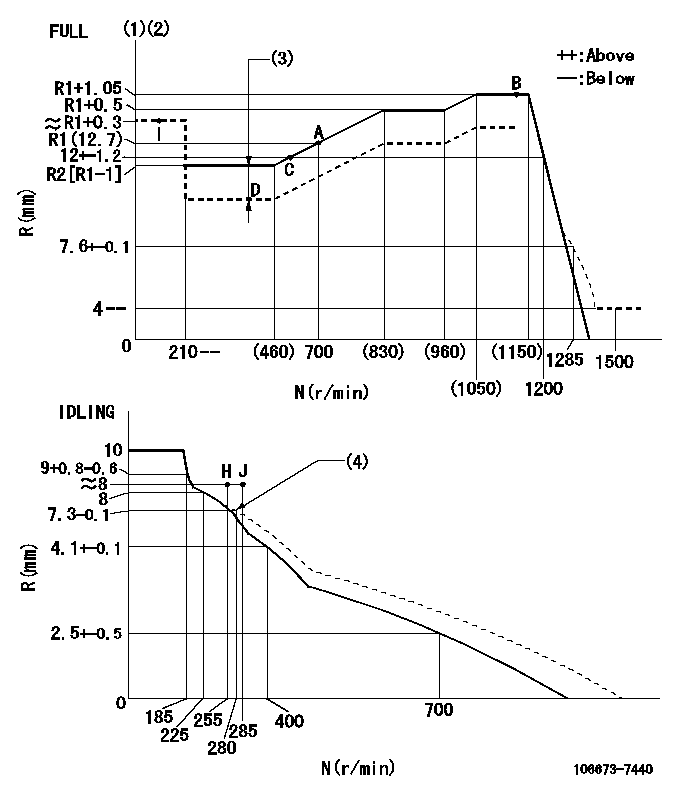
N:Pump speed
R:Rack position (mm)
(1)Torque cam stamping: T1
(2)Tolerance for racks not indicated: +-0.05mm.
(3)Boost compensator stroke: BCL
(4)Damper spring setting
----------
T1=AE12 BCL=(1.4)+-0.1mm
----------
----------
T1=AE12 BCL=(1.4)+-0.1mm
----------
Timer adjustment

(1)Adjusting range
(2)Step response time
(N): Speed of the pump
(L): Load
(theta) Advance angle
(Srd1) Step response time 1
(Srd2) Step response time 2
1. Adjusting conditions for the variable timer
(1)Adjust the clearance between the pickup and the protrusion to L.
----------
L=1-0.2mm N2=800r/min C2=(10)deg t1=2.5--sec. t2=2.5--sec.
----------
N1=750++r/min P1=0kPa(0kgf/cm2) P2=392kPa(4kgf/cm2) C1=10+-0.3deg R01=0/4load R02=4/4load
----------
L=1-0.2mm N2=800r/min C2=(10)deg t1=2.5--sec. t2=2.5--sec.
----------
N1=750++r/min P1=0kPa(0kgf/cm2) P2=392kPa(4kgf/cm2) C1=10+-0.3deg R01=0/4load R02=4/4load
Speed control lever angle
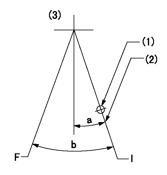
F:Full speed
I:Idle
(1)Use the hole at R = aa
(2)Stopper bolt set position 'H'
(3)Viewed from feed pump side.
----------
aa=37.5mm
----------
a=1deg+-5deg b=40.5deg+-3deg
----------
aa=37.5mm
----------
a=1deg+-5deg b=40.5deg+-3deg
Stop lever angle
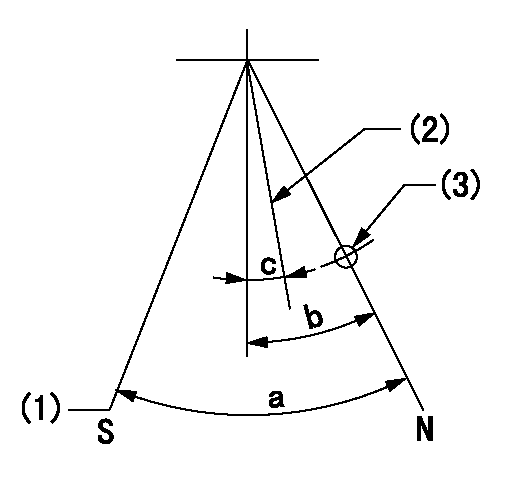
N:Pump normal
S:Stop the pump.
(1)At pump speed aa and rack position bb, set the stopper bolt. (Confirm non-injection.)
(2)Normal engine position (equivalent to R = cc).
(3)Use the hole above R = dd
----------
aa=1100r/min bb=3.5+-0.3mm cc=18mm dd=54mm
----------
a=40deg+-5deg b=29.5deg+-5deg c=(20.5deg)
----------
aa=1100r/min bb=3.5+-0.3mm cc=18mm dd=54mm
----------
a=40deg+-5deg b=29.5deg+-5deg c=(20.5deg)
0000001501 MICRO SWITCH
Adjustment of the micro-switch
Adjust the bolt to obtain the following lever position when the micro-switch is ON.
(1)Speed N1
(2)Rack position Ra
----------
N1=325r/min Ra=7.6+-0.1mm
----------
----------
N1=325r/min Ra=7.6+-0.1mm
----------
0000001601 RACK SENSOR

(VR) measurement voltage
(I) Part number of the control unit
(G) Apply red paint.
(H): End surface of the pump
1. Rack sensor adjustment (-0620)
(1)Fix the speed control lever at the full position
(2)Set the speed to N1 r/min.
(If the boost compensator is provided, apply boost pressure.)
(3)Adjust the bobbin (A) so that the rack sensor's output voltage is VR+-0.01.
(4)At that time, rack position must be Ra.
(5)Apply G at two places.
Connecting part between the joint (B) and the nut (F)
Connecting part between the joint (B) and the end surface of the pump (H)
----------
N1=1100r/min Ra=R1(12.7)+1.05mm
----------
----------
N1=1100r/min Ra=R1(12.7)+1.05mm
----------
Timing setting

(1)Pump vertical direction
(2)Coupling's key groove position at No 1 cylinder's beginning of injection
(3)B.T.D.C.: aa
(4)-
----------
aa=5deg
----------
a=(2deg)
----------
aa=5deg
----------
a=(2deg)
Information:
1. Remove plug (1) from the fuel injection pump housing.2. Use Tool (D) to loosen nut (2) for the fuel injection pump to be removed. Disconnect the fuel injection line nuts, and remove the felt washer. 3. Install Tool (A) in the fuel pump housing as shown with the square end down. Use a small amount of hand force to push down on Tool (A) while the control lever is moved forward to the "FUEL ON" position. Rack travel will stop in the center (zero) position. Hold a light forward force on the governor control lever to keep the fuel racks in the center (zero) position.4. Use Tool (B) to remove bushing (3) from the fuel injection pump housing. 5. Remove bushing (3) and O-ring seal (4).
When injection pumps, spacers and lifters are removed from the injection pump housing, keep the parts of each pump together so they can be installed in their original location.
6. Use Tool (C) to remove fuel injection pump (5). 7. Remove spacer (6) from the fuel injection pump housing. Make a note of the position from which each spacer was removed so each spacer can be installed in its original position.
Be careful when the fuel injection pumps are disassembled. Do not damage the surfaces of the plungers, barrels and bonnets. Any scratches will cause leakage inside the fuel injection pump. The plunger and barrel for each pump are made as a set. Do not put the plunger of one pump in the barrel of another pump. The check assemblies are made as a set. Do not mix the parts of the different check assemblies. Do not remove or make any adjustments of the gear segment on the plunger. It has been preset at the factory. If one part has wear, install a complete new pump assembly. Be careful when the plunger is put into the bore of the barrel.
8. Disassemble the fuel injection pump as follows: Remove ring (7). Separate bonnet (10) from barrel (9). Remove the spring and the check assembly from the bonnet. Remove plunger (8), the washer and spring from barrel (9).Install Fuel Injection Pumps
1. Inspect all parts for wear or damage. The plunger and barrel are serviced only as an assembly. 2. Put clean diesel fuel on plunger (1). Put plunger (1), washer (6) and spring (2) in position on barrel (3).3. Put check valve assembly (7) and spring (8) in bonnet (9). Connect bonnet (9) and barrel (3) together with ring (4). 4. Put spacer (10) into position in the pump housing bore. Be sure the correct spacer is with each pump. 5. Note the location of dowels (11) and (12) in the fuel injection pump housing. These dowels are for alignment of the fuel injection pump. 6. Slot (13) in gear segment (5) must align with dowel (11).7. Groove (14) must engage with dowel (12). 8. Use Tool (A) to put the fuel racks in the center (zero) position. See Remove Fuel Injection Pumps.9. Use Tool
Have questions with 106673-7440?
Group cross 106673-7440 ZEXEL
Mitsubishi
Mitsubishi
106673-7440
INJECTION-PUMP ASSEMBLY