Information injection-pump assembly
BOSCH
9 400 617 339
9400617339
ZEXEL
106673-7341
1066737341
MITSUBISHI
ME152019
me152019
Rating:
Cross reference number
BOSCH
9 400 617 339
9400617339
ZEXEL
106673-7341
1066737341
MITSUBISHI
ME152019
me152019
Zexel num
Bosch num
Firm num
Name
106673-7341
9 400 617 339
ME152019 MITSUBISHI
INJECTION-PUMP ASSEMBLY
6D24T1 K
6D24T1 K
Calibration Data:
Adjustment conditions
Test oil
1404 Test oil ISO4113 or {SAEJ967d}
1404 Test oil ISO4113 or {SAEJ967d}
Test oil temperature
degC
40
40
45
Nozzle and nozzle holder
105780-8250
Bosch type code
1 688 901 101
Nozzle
105780-0120
Bosch type code
1 688 901 990
Nozzle holder
105780-2190
Opening pressure
MPa
20.7
Opening pressure
kgf/cm2
211
Injection pipe
Outer diameter - inner diameter - length (mm) mm 8-3-600
Outer diameter - inner diameter - length (mm) mm 8-3-600
Overflow valve
131425-0220
Overflow valve opening pressure
kPa
157
123
191
Overflow valve opening pressure
kgf/cm2
1.6
1.25
1.95
Tester oil delivery pressure
kPa
255
255
255
Tester oil delivery pressure
kgf/cm2
2.6
2.6
2.6
Direction of rotation (viewed from drive side)
Right R
Right R
Injection timing adjustment
Direction of rotation (viewed from drive side)
Right R
Right R
Injection order
1-5-3-6-
2-4
Pre-stroke
mm
3.9
3.85
3.95
Beginning of injection position
Governor side NO.1
Governor side NO.1
Difference between angles 1
Cal 1-5 deg. 60 59.5 60.5
Cal 1-5 deg. 60 59.5 60.5
Difference between angles 2
Cal 1-3 deg. 120 119.5 120.5
Cal 1-3 deg. 120 119.5 120.5
Difference between angles 3
Cal 1-6 deg. 180 179.5 180.5
Cal 1-6 deg. 180 179.5 180.5
Difference between angles 4
Cyl.1-2 deg. 240 239.5 240.5
Cyl.1-2 deg. 240 239.5 240.5
Difference between angles 5
Cal 1-4 deg. 300 299.5 300.5
Cal 1-4 deg. 300 299.5 300.5
Injection quantity adjustment
Adjusting point
-
Rack position
12.9
Pump speed
r/min
700
700
700
Each cylinder's injection qty
mm3/st.
152.5
148.7
156.3
Basic
*
Fixing the rack
*
Standard for adjustment of the maximum variation between cylinders
*
Injection quantity adjustment_02
Adjusting point
Z
Rack position
8+-0.5
Pump speed
r/min
410
410
410
Each cylinder's injection qty
mm3/st.
21
17.8
24.2
Fixing the rack
*
Standard for adjustment of the maximum variation between cylinders
*
Injection quantity adjustment_03
Adjusting point
A
Rack position
R1(12.9)
Pump speed
r/min
700
700
700
Average injection quantity
mm3/st.
152.5
151.5
153.5
Basic
*
Fixing the lever
*
Boost pressure
kPa
24
24
Boost pressure
mmHg
180
180
Injection quantity adjustment_04
Adjusting point
B
Rack position
R1+0.95
Pump speed
r/min
1100
1100
1100
Average injection quantity
mm3/st.
143
139
147
Fixing the lever
*
Boost pressure
kPa
24
24
Boost pressure
mmHg
180
180
Injection quantity adjustment_05
Adjusting point
C
Rack position
(R1-0.7)
Pump speed
r/min
500
500
500
Average injection quantity
mm3/st.
149.5
143.5
155.5
Fixing the lever
*
Boost pressure
kPa
24
24
Boost pressure
mmHg
180
180
Injection quantity adjustment_06
Adjusting point
D
Rack position
(R2-1.5)
Pump speed
r/min
300
300
300
Average injection quantity
mm3/st.
103
101
105
Fixing the lever
*
Boost pressure
kPa
0
0
0
Boost pressure
mmHg
0
0
0
Boost compensator adjustment
Pump speed
r/min
300
300
300
Rack position
(R2-1.5)
Boost pressure
kPa
4
2.7
5.3
Boost pressure
mmHg
30
20
40
Boost compensator adjustment_02
Pump speed
r/min
300
300
300
Rack position
R2(R1-1)
Boost pressure
kPa
10.7
10.7
10.7
Boost pressure
mmHg
80
80
80
Test data Ex:
Governor adjustment
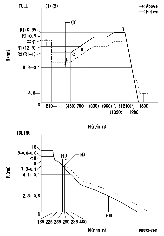
N:Pump speed
R:Rack position (mm)
(1)Torque cam stamping: T1
(2)Tolerance for racks not indicated: +-0.05mm.
(3)Boost compensator stroke: BCL
(4)Damper spring setting
----------
T1=AE93 BCL=(1.5)+-0.1mm
----------
----------
T1=AE93 BCL=(1.5)+-0.1mm
----------
Timer adjustment

(1)Adjusting range
(2)Step response time
(N): Speed of the pump
(L): Load
(theta) Advance angle
(Srd1) Step response time 1
(Srd2) Step response time 2
1. Adjusting conditions for the variable timer
(1)Adjust the clearance between the pickup and the protrusion to L.
----------
L=1-0.2mm N2=800r/min C2=(10)deg t1=2.5--sec. t2=2.5--sec.
----------
N1=750++r/min P1=0kPa(0kgf/cm2) P2=392kPa(4kgf/cm2) C1=10+-0.3deg R01=0/4load R02=4/4load
----------
L=1-0.2mm N2=800r/min C2=(10)deg t1=2.5--sec. t2=2.5--sec.
----------
N1=750++r/min P1=0kPa(0kgf/cm2) P2=392kPa(4kgf/cm2) C1=10+-0.3deg R01=0/4load R02=4/4load
Speed control lever angle
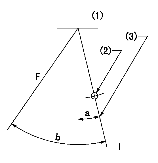
F:Full speed
I:Idle
(1)Viewed from feed pump side.
(2)Use the hole at R = aa
(3)Stopper bolt set position 'H'
----------
aa=37.5mm
----------
a=1deg+-5deg b=(42deg)+-3deg
----------
aa=37.5mm
----------
a=1deg+-5deg b=(42deg)+-3deg
Stop lever angle
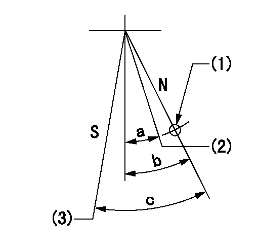
N:Pump normal
S:Stop the pump.
(1)Use the hole at R = aa
(2)Normal engine position (Rack position corresponding to bb)
(3)Set the stopper bolt so that speed = cc and rack position = dd (and confirm non-injection).
----------
aa=54mm bb=18mm cc=1100r/min dd=3.5+-0.3mm
----------
a=(20.5deg) b=29.5deg+-5deg c=40deg+-5deg
----------
aa=54mm bb=18mm cc=1100r/min dd=3.5+-0.3mm
----------
a=(20.5deg) b=29.5deg+-5deg c=40deg+-5deg
0000001501 RACK SENSOR

(VR) measurement voltage
(I) Part number of the control unit
(G) Apply red paint.
(H): End surface of the pump
1. Rack sensor adjustment (-0620)
(1)Fix the speed control lever at the full position
(2)Set the speed to N1 r/min.
(If the boost compensator is provided, apply boost pressure.)
(3)Adjust the bobbin (A) so that the rack sensor's output voltage is VR+-0.01.
(4)At that time, rack position must be Ra.
(5)Apply G at two places.
Connecting part between the joint (B) and the nut (F)
Connecting part between the joint (B) and the end surface of the pump (H)
----------
N1=1100r/min Ra=R1(12.9)+0.95mm
----------
----------
N1=1100r/min Ra=R1(12.9)+0.95mm
----------
Timing setting

(1)Pump vertical direction
(2)Coupling's key groove position at No 1 cylinder's beginning of injection
(3)B.T.D.C.: aa
(4)-
----------
aa=5deg
----------
a=(2deg)
----------
aa=5deg
----------
a=(2deg)
Information:
1. Disconnect fuel line (3) from the fuel transfer pump. Cap or plug immediately.2. Disconnect fuel line (4) from the fuel transfer pump. Cap or plug immediately.3. Remove bolts (1).4. Remove fuel transfer pump (2). Check the condition of the O-ring seal on the fuel transfer pump. If necessary, make a replacement. Put clean engine oil on the O-ring seal when assembling fuel transfer pump. For installation of the fuel transfer pump, reverse the removal steps.Disassemble & Assemble Fuel Transfer Pump
Start By:a. remove fuel transfer pump 1. Remove seal (1) from the fuel transfer pump.
Cover (2) is under spring tension. Remove the bolts that hold cover (2) slowly to prevent injury.
2. Remove bolts (3) and cover (2) the housing. 3. Remove seals (4) and valve (5) from cover (2). 4. Remove spring (6) from the piston.
Mark the orientation of valve (8) as to its location in the housing.
5. Remove washer (7) and valve (8) from the housing. 6. Remove piston (9) and sleeve (10) from the housing. 7. Remove seal (11) from sleeve (12). 8. Remove guide and tappet assembly (13) from the housing. 9. Remove seal (14) from guide (15).
If tappet (17) or guide (15) are damaged or worn, they must be replaced as a unit.
10. Remove ring (16) from tappet (17) and the tappet from guide (15). 11. Remove the bolts and cover (18) from the housing. 12. Remove seal (19) from cover (18). 13. Remove valve (20) from the housing. The following steps are for the assembly of the fuel transfer pump.14. Install valve (20) in the housing. Put clean fuel on seal (19) and install it on cover (18). Install the cover on the housing.15. Install tappet (17) in guide (15). Install ring (16) on tappet (17) to hold the tappet in the guide.16. Put clean fuel on seal (14) and install it on the guide and tappet assembly (13). Install guide and tappet assembly (13) in the housing.17. Put clean fuel on seal (11) and install it on sleeve (12). Install sleeve (12) in the housing.18. Install piston (9) in the housing. Install valve (8) and washer (7) in the housing. Install spring (6) in the piston.19. Install valve (5) in cover (2).20. Put clean fuel on seals (4) and put them in position on cover (2). Install cover (2) on the housing.21. Put seal (1) in position on the fuel transfer pump.End By:a. install fuel transfer pump
Have questions with 106673-7341?
Group cross 106673-7341 ZEXEL
Mitsubishi
Mitsubishi
Mitsubishi
Mitsubishi
106673-7341
9 400 617 339
ME152019
INJECTION-PUMP ASSEMBLY
6D24T1
6D24T1