Information injection-pump assembly
ZEXEL
106673-7340
1066737340
Rating:
Cross reference number
ZEXEL
106673-7340
1066737340
Zexel num
Bosch num
Firm num
Name
106673-7340
INJECTION-PUMP ASSEMBLY
Calibration Data:
Adjustment conditions
Test oil
1404 Test oil ISO4113 or {SAEJ967d}
1404 Test oil ISO4113 or {SAEJ967d}
Test oil temperature
degC
40
40
45
Nozzle and nozzle holder
105780-8250
Bosch type code
1 688 901 101
Nozzle
105780-0120
Bosch type code
1 688 901 990
Nozzle holder
105780-2190
Opening pressure
MPa
20.7
Opening pressure
kgf/cm2
211
Injection pipe
Outer diameter - inner diameter - length (mm) mm 8-3-600
Outer diameter - inner diameter - length (mm) mm 8-3-600
Overflow valve
131425-0220
Overflow valve opening pressure
kPa
157
123
191
Overflow valve opening pressure
kgf/cm2
1.6
1.25
1.95
Tester oil delivery pressure
kPa
255
255
255
Tester oil delivery pressure
kgf/cm2
2.6
2.6
2.6
Direction of rotation (viewed from drive side)
Right R
Right R
Injection timing adjustment
Direction of rotation (viewed from drive side)
Right R
Right R
Injection order
1-5-3-6-
2-4
Pre-stroke
mm
3.9
3.85
3.95
Beginning of injection position
Governor side NO.1
Governor side NO.1
Difference between angles 1
Cal 1-5 deg. 60 59.5 60.5
Cal 1-5 deg. 60 59.5 60.5
Difference between angles 2
Cal 1-3 deg. 120 119.5 120.5
Cal 1-3 deg. 120 119.5 120.5
Difference between angles 3
Cal 1-6 deg. 180 179.5 180.5
Cal 1-6 deg. 180 179.5 180.5
Difference between angles 4
Cyl.1-2 deg. 240 239.5 240.5
Cyl.1-2 deg. 240 239.5 240.5
Difference between angles 5
Cal 1-4 deg. 300 299.5 300.5
Cal 1-4 deg. 300 299.5 300.5
Injection quantity adjustment
Adjusting point
-
Rack position
12.9
Pump speed
r/min
700
700
700
Each cylinder's injection qty
mm3/st.
147
143.3
150.7
Basic
*
Fixing the rack
*
Standard for adjustment of the maximum variation between cylinders
*
Injection quantity adjustment_02
Adjusting point
Z
Rack position
8+-0.5
Pump speed
r/min
385
385
385
Each cylinder's injection qty
mm3/st.
21
17.8
24.2
Fixing the rack
*
Standard for adjustment of the maximum variation between cylinders
*
Injection quantity adjustment_03
Adjusting point
A
Rack position
R1(12.9)
Pump speed
r/min
700
700
700
Average injection quantity
mm3/st.
147
146
148
Basic
*
Fixing the lever
*
Boost pressure
kPa
23.3
23.3
Boost pressure
mmHg
175
175
Injection quantity adjustment_04
Adjusting point
B
Rack position
R1+1.05
Pump speed
r/min
1100
1100
1100
Average injection quantity
mm3/st.
143.5
139.5
147.5
Fixing the lever
*
Boost pressure
kPa
23.3
23.3
Boost pressure
mmHg
175
175
Injection quantity adjustment_05
Adjusting point
C
Rack position
(R1-0.75
)
Pump speed
r/min
500
500
500
Average injection quantity
mm3/st.
142
136
148
Fixing the lever
*
Boost pressure
kPa
23.3
23.3
Boost pressure
mmHg
175
175
Injection quantity adjustment_06
Adjusting point
D
Rack position
(R2-1.3)
Pump speed
r/min
300
300
300
Average injection quantity
mm3/st.
104.5
102.5
106.5
Fixing the lever
*
Boost pressure
kPa
0
0
0
Boost pressure
mmHg
0
0
0
Boost compensator adjustment
Pump speed
r/min
300
300
300
Rack position
(R2-1.3)
Boost pressure
kPa
4
2.7
5.3
Boost pressure
mmHg
30
20
40
Boost compensator adjustment_02
Pump speed
r/min
300
300
300
Rack position
R2(R1-1)
Boost pressure
kPa
10.7
10.7
10.7
Boost pressure
mmHg
80
80
80
Test data Ex:
Governor adjustment
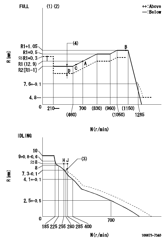
N:Pump speed
R:Rack position (mm)
(1)Torque cam stamping: T1
(2)Tolerance for racks not indicated: +-0.05mm.
(3)Damper spring setting
(4)Boost compensator stroke: BCL
----------
T1=AC25 BCL=(1.3)+-0.1mm
----------
----------
T1=AC25 BCL=(1.3)+-0.1mm
----------
Timer adjustment

(1)Adjusting range
(2)Step response time
(N): Speed of the pump
(L): Load
(theta) Advance angle
(Srd1) Step response time 1
(Srd2) Step response time 2
1. Adjusting conditions for the variable timer
(1)Adjust the clearance between the pickup and the protrusion to L.
----------
L=1-0.2mm N2=800r/min C2=(10deg) t1=2.5--sec. t2=2.5--sec.
----------
N1=750++r/min P1=0kPa(0kgf/cm2) P2=392kPa(4kgf/cm2) C1=10+-0.3deg R01=0/4load R02=4/4load
----------
L=1-0.2mm N2=800r/min C2=(10deg) t1=2.5--sec. t2=2.5--sec.
----------
N1=750++r/min P1=0kPa(0kgf/cm2) P2=392kPa(4kgf/cm2) C1=10+-0.3deg R01=0/4load R02=4/4load
Speed control lever angle
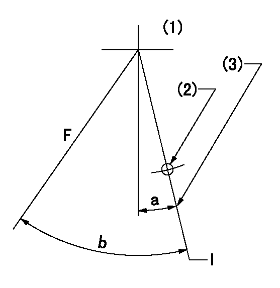
F:Full speed
I:Idle
(1)Viewed from feed pump side.
(2)Use the hole at R = aa
(3)Stopper bolt set position 'H'
----------
aa=37.5mm
----------
a=1deg+-5deg b=(39deg)+-3deg
----------
aa=37.5mm
----------
a=1deg+-5deg b=(39deg)+-3deg
Stop lever angle
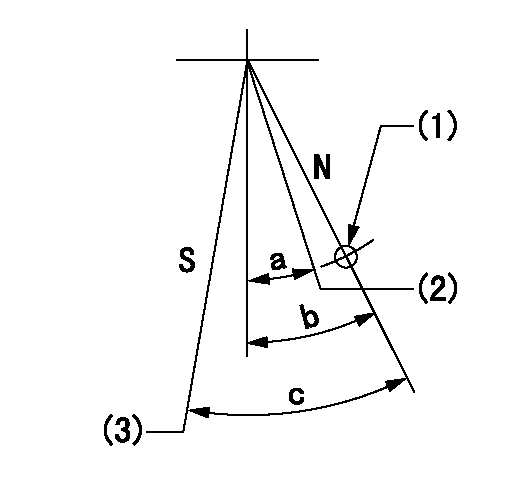
N:Pump normal
S:Stop the pump.
(1)Use the hole at R = aa
(2)Normal engine position (Rack position corresponding to bb)
(3)Set the stopper bolt so that speed = cc and rack position = dd (and confirm non-injection).
----------
aa=54mm bb=18mm cc=1100r/min dd=3.5+-0.3mm
----------
a=(20.5deg) b=29.5deg+-5deg c=40deg+-5deg
----------
aa=54mm bb=18mm cc=1100r/min dd=3.5+-0.3mm
----------
a=(20.5deg) b=29.5deg+-5deg c=40deg+-5deg
0000001501 RACK SENSOR

(VR) measurement voltage
(I) Part number of the control unit
(G) Apply red paint.
(H): End surface of the pump
1. Rack sensor adjustment (-0620)
(1)Fix the speed control lever at the full position
(2)Set the speed to N1 r/min.
(If the boost compensator is provided, apply boost pressure.)
(3)Adjust the bobbin (A) so that the rack sensor's output voltage is VR+-0.01.
(4)At that time, rack position must be Ra.
(5)Apply G at two places.
Connecting part between the joint (B) and the nut (F)
Connecting part between the joint (B) and the end surface of the pump (H)
----------
N1=1100r/min Ra=R1(12.9)+1.05mm
----------
----------
N1=1100r/min Ra=R1(12.9)+1.05mm
----------
Timing setting

(1)Pump vertical direction
(2)Coupling's key groove position at No 1 cylinder's beginning of injection
(3)B.T.D.C.: aa
(4)-
----------
aa=5deg
----------
a=(2deg)
----------
aa=5deg
----------
a=(2deg)
Information:
If fuel line clamps are not installed in their exact location, vibration can cause the fuel lines to break and cause possible personal injury, or damage to the machine.
1. Disconnect front fuel injection lines (1), disconnect middle fuel injection lines (2) and rear fuel injection lines (3) from the fuel injection pump and the cylinder head assembly.2. Remove fuel injection lines (1), (2) and (3). Put caps or plugs on all fuel line connections to keep foreign material out of the fuel system.3. If a separation of the fuel lines has to be made, make sure the exact location of the clamps are marked for assembly purposes. Remove the clamps and make a separation of the fuel lines. The following steps are for the installation of the fuel injection lines.4. Remove the caps or plugs for the fuel injection line connections.5. If removed, connect the fuel lines with the clamps. Make sure the clamps are installed back in their correct location. Use Tool (A) to tighten the clamp bolts to a torque of 2.3 N m (20 lb in). For more information, see Specifications Manual SENR6470, of Testing & Adjusting Manual SENR6471.6. Install front fuel injection lines (1) on the fuel injection pump and cylinder head assembly.7 Install middle fuel injection lines (2) on the fuel injection pump and the cylinder head assembly.8. Install rear fuel injection lines (3) on the fuel injection pump and the cylinder head assembly.9. Tighten the fuel injection line nuts to a torque of 40 7 N m (30 5 lb ft).
Have questions with 106673-7340?
Group cross 106673-7340 ZEXEL
Mitsubishi
Mitsubishi
Mitsubishi
106673-7340
INJECTION-PUMP ASSEMBLY